Here is a simple project called listening bug circuit using 741 using the most popular op-amp IC 741. This circuit can be used for spying because by using this circuit we can hear any conversation held in any other room or we can say using this circuit one can hear the conversation held in another room. This circuit can also be used for baby monitoring. Also, check our Listening Bug Circuit using op-amp LM386.
Description of Listening Bug Circuit Using 741
The circuit of the listening bug shown in figure 1 comprises an op-amp IC 741, one complimentary pair transistor (One NPN and one PNP transistor), a loudspeaker, a microphone, and a few other passive components like a resistor and capacitor. A microphone is a transducer that converts the audio signal to voltage in the range of milli which further needs amplification. A long wire from the microphone is connected to inverting input (pin 2) of IC1 through resistor R2 and capacitor C1. The output of IC1 from pin 6 is given to the base of transistors T1 and T2.
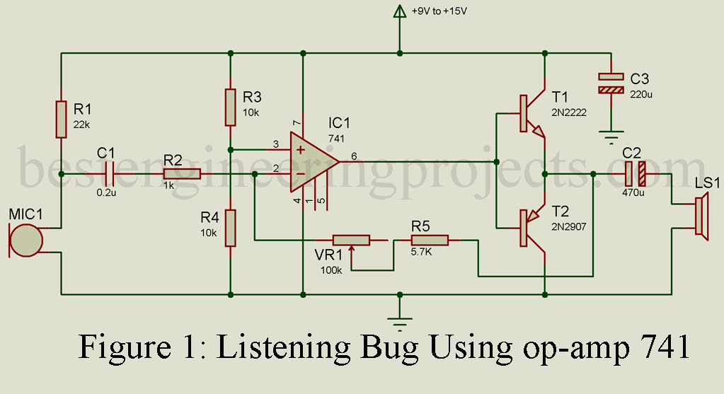
A voltage divider network is designed using two 10K resistors (R3 and R4) to set reference voltage at a non-inverting pin (Pin 3). Pure DC power supply of 9V to 15V is given pin 7 whereas pin 4 is grounded. The feedback network is designed using one resistor (R5) and one variable resistor (VR1) as shown in the figure. The amplified output is taken from pin 6 which is used to drive the complementary pair transistor (T1 and T2). There we used complementary pairs to provide more power to the speaker. Capacitor C2 is used to filter out the DC component if available.
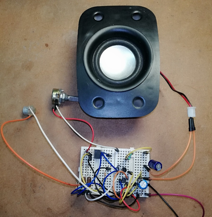
Figure 2: Author Prototype of Listening Bug using Op-Amp 741
Note: If a hissing sound is came from the speaker, then you have to change the power supply unit because we need a Pure DC power supply unit. We recommend you use the battery if possible. Capacitor C3 is used here to smooth the DC power supply. Before using the microphone and speaker, please check the appropriate polarity of these two components.
PCB Board:
PCB board is designed using Proteus 8.1, Solder side PCB, and Component side PCB, and 3D design is shown in Figures 3, 4, and 5 respectively. The image shown below is scaled at 200%. Download the PCB diagram in PDF from the link given below.
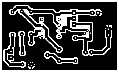
Figure 3: Solder Side PCB Diagram
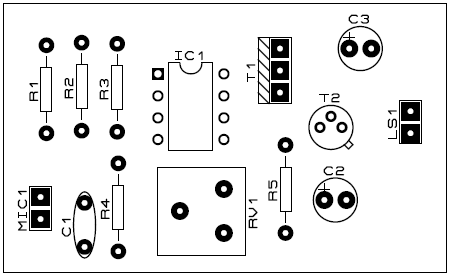
Figure 4: Component side PCB Diagram
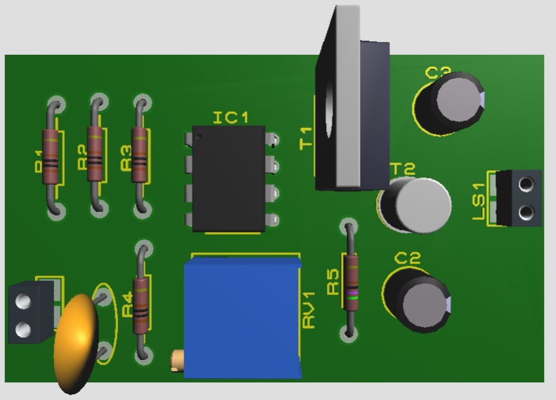
Figure: 3D View of PCB Diagram
Click Here to download the PCB Diagram for Listening Bug
PARTS LIST OF LISTENING BUGS USING OP-AMP 741
|
Resistor (all ¼-watt, ± 5% Carbon) |
| R1 = 22 KΩ
R2 = 1 KΩ R3, R4 = 10 KΩ R5 = 5.7 KΩ VR1 = 100 KΩ |
| Capacitors |
|
C1 = 0,2 µF (Ceramic Disc) C2 = 470 µF/25V (Electrolytic Capacitor) C3 = 250 µF/25V (Electrolytic Capacitor) |
| Semiconductors |
| IC1 = LM741 (General Purpose operational amplifier)
T1 = 2N2222 (General Purpose Silicon NPN Transistor) T2 = 2N2907 (General Purpose Silicon PNP Transistor) |
| Miscellaneous |
| MIC1 = Condenser microphone
LS1 = 4Ω loudspeaker |
If we do not find the required resistors and we use different resistors instead of the ones mentioned, does it make any difference on the overall circuit?
You may get the required value of resistor using series or parallel connection
Will we get the desired output even if we don’t use the resistor R5 ?
We used R5 for impedance matching, and it is required to get desire output.
as I can make it work. or how I can check its functionality
The circuit posted above is 100% working and you can use it in many application.
E.g To monitor children, class room etc.
Can we have any alternative for Op-amp? Coz it requires +/- 12 v.
The circuit posted here uses only single polarity DC volt (+9v) or you can also uses 9V battery. instead of power supply circuit.
can I use BC547 for T1 and BC557 for T2
I had not checked yet, but you may use with possible modification.
Is it mandatory to use only 4ohm loud speaker or can i use any other
The circuit works proper with 4-ohm output load, you can also use headphone.
how to calculate the values of components????like how you know whcih resistor and transistors are to be used????
I built this circuit and the audio signal I got was very low and mixed with other noises even in quiet places. The only difference I made was the speaker. I was using an 8ohm loud speaker. Is the loud speaker the problem? Thanks in advance.
I had modified the circuit, now you will get output.
I had modified the circuit, now reconnect according to the circuit diagram you will definitely get output. If it’s work leave a comment. :)
Can we use 1 mega variable resistor instead of 2mega…2 mega is not available in market
It might work, if you cannot achieve the desire output then add a series resistor network.
The circuit finally worked ☺but the only problem is that it does not pick up weak signals… You have to practically scream into the microphone
Can you please give some explanation as to how the circuit works. I’m not able to figure it out.
What is the significance of the variable resistor 2M ohms
Variable resistor 2M is used to adjust gain of the circuit.
Can we use wireless speaker coz it’s very efficient
In case of using wireless speaker what did I want to do ????
can i replace the 250 uf cap to a 220 uf cap since 250 uf is not standard in our marketplace.