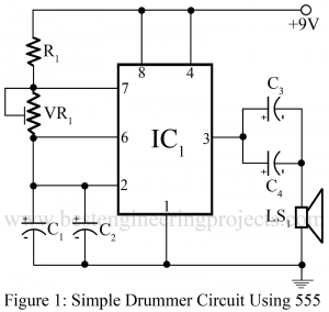
Electronic Pendulum Using NE555

circuit diagram of electronic pendulum using 555

Here is a simple, cheap and vary interesting electronic pendulum. The project electronic pendulum using NE555 can be used in various other gadgets i.e. it can be used in digital clock for pendulum view. Circuit Description of Electronic Pendulum Using NE555: The circuit of electronic pendulum comprises a timer IC NE555 (IC1), CD7400 (IC2), 4-bit up-down counter IC CD74193 (IC3) and a BCD to decimal decoder IC 7442 (IC4). Timer IC NE555 (IC1) is configures in astable multivibrator mode and generate square wave. The frequency of square wave generating from…

Read More

20W Audio Amplifier Using TDA2020

circuit diagram of 20W audio amplifier using tda2020

20W Audio Amplifier Using TDA2020 Here is one another circuit in the series of audio power amplifier. We had already posted audio amplifier using transistor (3Watt, 10Watt and 20Watt) and using IC (7Watt and 20Watt). We used here IC TDA2020 for designing audio amplifier circuit. TDA2020 (IC1) can deliver a maximum of 20Watt into a 4Ω loads. Like the TBA810, the TDA2020 also incorporated thermal shutdown, and output short-circuit protection. The input impedance of the circuit 20Watt audio amplifier using TDA2020 is determined by resistor R1 and sensitivity is determined…

Read More

7W audio amplifier using TBA810

circuit diagram of 7W audio amplifier using tba810

Here is another circuit in the series of audio power amplifiers. Previously we had already posted 3W and 20W audio amplifiers using transistors. Now we use an integrated circuit instead of transistors for designing audio amplifier circuits. By using IC TBA810 one can get a power output of 7W. The audio power amplifier featuring the TBA810 integrated circuit is shown in figure 1. This IC incorporated build-in-terminal shutdown, which automatically reduces the output in the event of sustained overloads or if the heat sinking arrangement is inadequate. We use a…

Read More

Advance Mini UPS Circuit

author prototype for mini ups

Mobile phones and small electronic gadgets are powered by AC mains using an AC adapter. In the event of mains failure, a low-capacity UPS will do the job satisfactorily. Here we design a simple, efficient, economical, and easy-to-construct UPS for mobile phone or telephone sets. The project advanced mini-UPS circuit can also be used for high power by changing a transformer with a high current rating so this circuit can be used as power backup for laptops also. We have already posted 350VA Offline UPS Circuit. Block Diagram of Advance…

Read More

Beeper Circuit using Timer IC 555

circuit diagram of beeper using timer ic 555

Here is a beeper circuit employing two timer ICs NE555 (IC1 and IC2). The beeper circuit using timer IC NE555 can be used in various circuits that require an alarm or a ‘beeping’ signal. Description of Beeper Circuit Using Timer IC NE555 Timer IC1 is  used here  in astable mode in such a way that square-wave output at about 1 Hz is obtained. IC2 is also configure  in astable mode, but it gives an output with about 1 kHz frequency. The output if IC1 (pin 3) is connected to ‘Reset’…

Read More

Advance Emergency Light Circuit

block diagram of emergency light

Many types of emergency light circuits are already available in the web world. Now, here is a unique circuit that glows a fluorescent tube at a voltage as low as 80 volts. This unique circuit Advance Emergency Light Circuit operates at a 12V battery and also charges the battery up to 12V, 15AH at a constant rate. Block Diagram of Advance Emergency Light Circuit The block diagram of the advanced emergency light circuit with charger unit is shown in figure 1. It consists of a power supply for emergency light,…

Read More

Photoelectric switch using ne555

circuit diagram of photoelectric switch using 555

This circuit is of a highly sensitive photoelectric switch using NE555 timer IC. When the LDR1 is kept in light, the switch remains off, but when the light source is removed, the controller circuit gets switched on. This switch has vast application. With little modification, it can be used as a burglar alarm, a corridor visitors monitor, an automatic street lighting system, and as an automatic water tap system. Circuit Description of | Photoelectric switch using NE555 The NE555 timer functions here as a Schmitt trigger. A NE555 IC comprises two…

Read More

Medium Speed Modem Using SC11004

circuit diagram of medium speed modem

Modems have been often been stand-alone, add-on devices for most data communications equipment. The recent integration of the complex functions a modem performs into a single chip has allowed manufacturers to economically build the modem right into the microcomputer or data terminal equipment. A circuit diagram of such a modem is shown in figure 1. Circuit Description of Medium Speed Modem Using SC11004 All of the signal processing functions needed for a full-duplex, 300/1200-b/s modem, including the FSK and PSK modulators and de-modulators, are integrated on a single chip. It includes…

Read More

Water Level Controller Using NE555

circuit diagram of water level controller

Here is a circuit called Water Level Controller Using 555  which continuously monitors the level in the overhead and ground-level tanks, and switches on the pump whenever the water level in the overhead tanks falls below a predetermined level and switches off the pump whenever it reaches the maximum preset level so that there is no spillage. Further, if the level of water in the lower tank falls below a preset low level, this circuit overrides the commands being sensed from the overhead tank and switches off the pump. This…

Read More

20W Audio Amplifier Using ECN149-ECP149 Pair Transistor

circuit diagram of 20W audio amplifier

High wattage power transistor is matched complementary pair are now readily available. Using such transistor, an economical high power amplifier using a minimum of components and giving a good performance can easily by constructed by an audio enthusiast. Thus, here we had designed a 20W Audio Amplifier Using ECN149-ECP149 Pair Transistor. Circuit Description of 20W Audio Amplifier Using Ecn149-ECP149 Pair Transistor A discrete power amplifier circuit is shown in figure 1 employs the 30W silicon output transistor pair ECN149-ECOP49. This amplifier will deliver 20W into 8Ωwith a 450mV input signal. We…

Read More