An audio mixer circuit is used to combine output from several microphones/channels into one or more common outputs, usually for public address purposes or while recording. The function of the audio mixture circuit, as the name suggests is to ‘mix’ the different audio signals which are fed to the input for the mixer. In this article, we include various types of audio mixer circuits from the simplest possible transistor audio mixer circuit to the high-end audio mixer preamplifier using an operational amplifier.
Description and Working of Audio Mixture Circuit
The circuit of the simplest transistor audio mixture circuit is shown in figure 1. This circuit has a low input impedance and the three channels are not isolated prior to mixing. Thus the impedance of each channel is dependent to some extent on the setting of the potentiometer controlling the other channel. Here resistors R1 through R4 set the voltage gain at unity. Capacitor C1 through C4 is the DC blocking capacitor and potentiometer VR1 through VR3 is the feeder control for channels 1 to 3 respectively. The audio mixer circuit is working as the current adding circuit.

Improved Audio Mixture Circuit
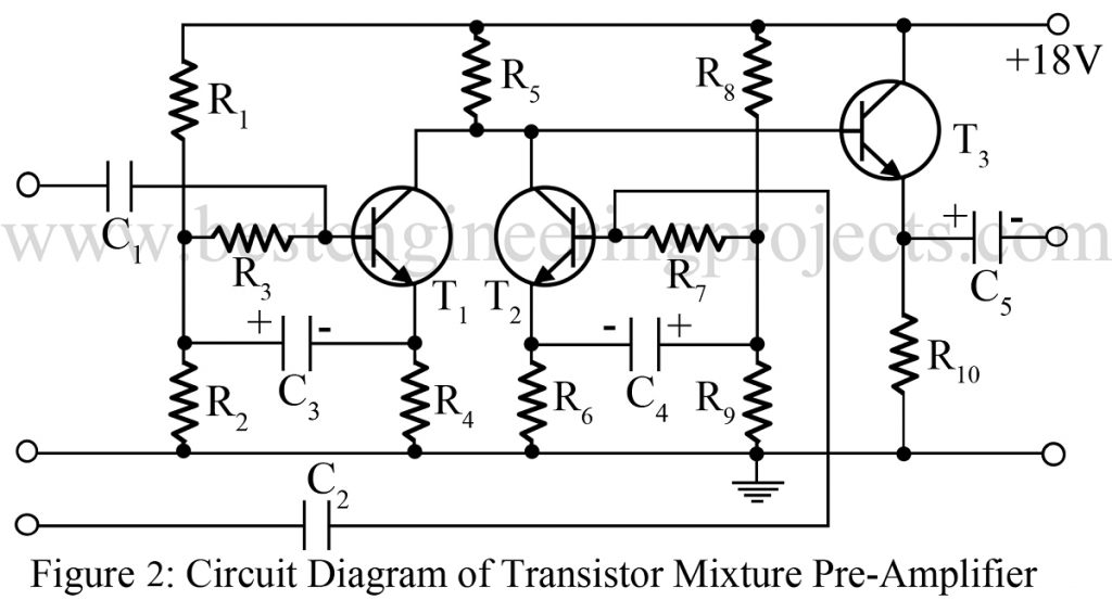
An improved transistor audio mixer circuit is given in figure 2. Here each input is fed to a separate transistor. Bootstrapping ensures a high input impedance of more than 1 M. All the input transistors share a common collector to load resistor. The following emitter–follower stage ensures a low output impedance (less than 100). As in the above circuit capacitor, C1 through C3 is the DC blocking capacitors.
Equivalent Audio Mixture Circuit
An IC equivalent to the simplest transistor audio mixer circuit of figure 1 is shown in figure 3. This circuit is basically that of an inverting amplifier, but with each input channel having its own input resistors. With just one input signal fed to the amplifier, it acts as an inverting amplifier with R1 and R6 setting the voltage gain at unity. C1 is the DC blocking capacitor and VR1 is the feeder control for channels.
When two or more inputs are used, it functions as a sort of current-adding circuit. The voltage at the output is the sum of the input signals fed to the inverting input of the op-amp (pin 2). The audio mixer circuit works as a high-quality mixer.

Another audio mixer circuit using the LM349 is given in circuit 4. Here each input is fed to a separate op-amp: the input is given to the inverting input of op-amp through its own input resistor as shown in the circuit diagram. After suitable buffering and amplification they are mixed by the last op-amp (N4). The output is taken from pin 14.

Hi there!
I found these preamp and mixer circuits very interesting. Although for “figure2: circuit diagram of transistor mixer pre-amplifier” the component values are missing.
Either that or I couldn’t find them, could you please point me in the right direction?
Thanks