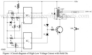
Bass Treble Circuit

circuit diagram of bass treble unit

Among different types of amplifiers available in today’s technical world, sometimes we get stuck with the audio frequency amplifiers which provide flat frequency low-frequency notes should be amplified more than the high-frequency note stable). The provision of bass treble is accordingly made to gratify the users and to compensate for the effect of noise that comes along with the signal. The bass treble combination is given a single name; tone control. Circuit Description of Bass Treble Circuit Talking about the bass treble circuit, it is comparatively much simpler and gainful.…

Read More

Water Level Indicator Circuit using 7-Segment

circuit diagram of water level indicator

Normally we have seen on different websites, the overall circuit of the water level indicator uses a bar graph or a seven-segment display to indicate the water level. This type of representation using LEDs or digits for water level makes the observer which includes a large number of normal people, difficult to understand. A consequence of using those methods makes the whole effort inadequate. The circuit presented below surmounts this flaw and displays the water level using a seven-segment display, but there is a difference. The water level indicator circuit…

Read More

Electronic Code Lock Circuit

circuit diagram of electronic code lock

Using codes for security has been a popular trend recently. A similar type of electronic project is presented right below called the electronic code lock circuit which ensures the use of four digits in the code locking process and these codes are keyed in remotely. The code can be unlocked easily by pressing the right keys and if someone presses the wrong keys, it resets the lock automatically. The complete phenomenon of the electronic code lock systems has been described briefly in the further paragraph. Description and Working of Electronic…

Read More

Add on Device For Telephone

circuit diagram of add on unit for telephone

This electronic project, Add on Device For Telephone has multiple applications when used with the telephone lines. Since it is added parallel on the telephone system, it is called add-on device. The circuit add on device for telephone supports three modes of operation: on-hook, off hook, and ringing modes. It also provides the audio-visual indication of these operations. Using the relay, add on device circuit can connect the telephone to a CID (caller identification device). It can also be used to indicate tapping or misuse of telephone lines with the…

Read More

Tone Control Circuit (Active and passive)

circuit diagram of active tone control using single transistor

Among the most popular control circuit found in an audio system is tone control. The tone control is used to modify the tonal characteristic of the signal chain i.e. it enables the listener to alter the tonal quality of the sound being reproduced. The effect of tone control has on the frequency response of the equipment and their purpose is to help remedy shortcomings in the source program material, the receiver or transducer, or in the loudspeaker and the listening room combination. These are either of the passive types, of…

Read More

Phone Broadcaster Circuit

circuit diagram of phone broadcaster

An interesting circuit design that is also used as a wireless telephone amplifier, is demonstrated below which has been proven very useful in prying on a telephone conversation and therefore is termed a phone broadcaster circuit. The more amazing or we can say a comforting fact about the phone broadcaster circuit design is that it draws the power essential to operate the circuit directly from the active telephone lines. Therefore, it avoids additional expenses in external battery and prevents the circuit from the extra bulkiness of other power supplies. Circuit…

Read More

Forced Frequency Dependent Exciting Force with Viscous Damping

responsive curve for rotating spring

Introduction to Forced Frequency Dependent Exciting Force with Viscous Damping Some machines like Turbo-generators produce unbalanced force which imparts into the foundation-soil system frequency dependent exciting force. In Turbo generators two counteracting masses are placed at an eccentricity, e. This is shown in Figs. 1(a) and (b). The masses are so placed that they reach the top simultaneously. The rotating force of each mass is given by,  ———-(1) Referring to the figure and resolving the force horizontally and vertically we got the total vertical force as:    ———-(2) And horizontal forces…

Read More

Forced Vibration of a Mass Spring System with Damping

forced mass spring dashpot system

In foundation soil system damping is always present in one form or another. For this case fig. 1 (a), the equation of motion is:   ———-(1)   ———-(2) The solution of equation (2) is done by applying the concept of rotating vector. In the figure 1 the exciting force vector Q­0 is placed with a phase angle ahead of the displacement vector A. The equation of displacement may be expressed as:   ———-(3) In figure 1 (b) the position of motion vector is shown. In figure 1 (c) the position…

Read More

Forced Vibration of a Mass Spring System without Damping

force vibration of mass and spring

In the case forced vibration of a mass spring system without damping the mass spring system is acted by a periodic oscillation force and the damping is absent. Unbalanced rotating machinery such as compressor piston produces such type of motion. This is shown in fig.1 (a). For this case the equation of motion can be written as: ———-(1) The solution of equation includes the solution for free vibration and solution satisfying the right hand side. Concept of rotating vector is used to solve the equation (1). s per the vector…

Read More

Free Vibration of a Mass Spring System with Damping

free vibration system with viscous damping

Fig.1 (a) shows the free vibration of a system with damping. A device known as damper is shown in the figure below. The damping force acts in the opposite direction to that of oscillating mass. The equation of motion for this case can be written as:   ———-(1) Where, c = coefficient of viscous damping Or,   ———-(2)   Or,   ———-(3)   Put then     And   ———-(4) By substituting the value in equation (3) we have,   ———-(5) The solution for can be written as:   ———-(6)…

Read More