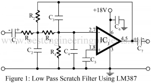
Adjustable Ripple-Regulated Power Supply Using 741

circuit diagram of adjustable ripple regulated power supply

Many instruments and equipment, such as function generators, transmitters, trans-receivers, high-quality stereo systems, and radio receivers, require ripple-free power supplies. The most significant feature required in a good quality power supply, besides load and line regulation, is minimum ripple as its output. Circuit Description of Adjustable Ripple-Regulated Power Supply Using 741 In various applications where the ripple is not desired, the circuit adjustable ripple-regulated power supply using 741  shown in figure 1 for adjustable ripple regulated power supply works quite satisfactorily. Here the advantage of op-amps’ enormous gain is utilized along…

Read More

3watt Audio Amplifier Using AC187-AC188 Pair

circuit diagram of 3W audio amplifier

The high wattage power transistor with matched complementary pair is now readily available. Using such a transistor, an economical high power amplifier using a minimum of components and giving a good performance can easily be constructed by an audio enthusiast. Here in this article, we are going to build a 3watt audio amplifier by using complementary pair of transistors. Circuit Diagram of 3watt Audio Amplifier Using AC187-AC188 Pair A discrete 3watt Audio power amplifier circuit is shown in figure 1 employs a complementary output stage featuring the AC 187-AC188 (T3…

Read More

Sequential Timer Circuit Using NE555

circuit diagram of sequential timer using 555

This is a simple sequential timer circuit using NE555 which can be used for psychedelic light, decoration in shops, advertisement boards at night, and parties. The circuit is similar to those published earlier, except for the fact that it incorporates some additional features. Circuit Description Sequential Timer Using NE555 In the circuit sequential timer circuit IC2, IC3 and IC4 are used as monostable multivibrators. The trigger terminals (pins 2) of these ICs are connected in a chain to the previous ICs through an RC differentiator network (0.022 µF capacitor and…

Read More

A Variable Audio Frequency Oscillator Using Op-amp 741

circuit diagram of variable audio frequency oscillator

The frequency of the AF oscillator can be varied over a wide range. It can therefore be used for AF amplifier testing and also as a code practice oscillator. Circuit Description of A Variable Audio Frequency Oscillator Using Op-amp 741 The circuit of variable audio frequency oscillator using op-amp 741 is mainly a Wein Bridge oscillator whose frequency is varied using the gang condenser. While using the IC1 741 (operational amplifier), the use of a split power supply has been avoided by using capacitors C1 and C2, for R4*, a 150-Ω…

Read More

Pulse Width Modulation using 565 IC

circuit diagram of pll generation of pwm and ppm

Pulse Width Modulation (PWM) is a technique to control the average power delivered to the analog devices. With an acquisition of 555 IC amongst most people working with electronic devices, the use of 565 IC is like using two 555 ICs inside a single device. Unlike 555 IC, 565 IC has 14 pins which act as a dual timer. 565 IC is also available with 10 pins.  Nevertheless, they both require the same amount of power supply. PWM using 565 IC is a form of Pulse Time Modulation (PTM), also…

Read More

PWM Generator and Class D Power Amplifier

circuit diagram of pwm generator and class d power amplifier

PWM (pulse-width modulation) forms the basis for a very efficient form of power amplification. The circuit in figure 1 is a so-called class D power amplifier since the actual power amplification is provided to the PWM signal, and since it is of constant amplitude. The transistors used can function between cutoff and saturation. This allows for maximum efficiency (over 90%) and is the reason for the increasing popularity of class D amplifiers as a means of amplifying any analog signal. Circuit Description of PWM Generation Class D Power Amplifier The…

Read More

Frequency Shift Keying (FSK) Generator Using PLL 565

circuit diagram of frequency shift keying (fsk) generator

The generation of frequency shift keying (FSK) can be easily accomplished by switching an additional capacitor into the tank circuit of an oscillator when the transmitter is keyed, in narrowband frequency shift keying (FSK) it is often possible to get the required frequency shift by shunting the capacitance directly across a crystal, especially if frequency multiplier follow the oscillator, as is usually the case. Circuit Description of Frequency Shift Keying (FSK) Generator Using PLL 565 Frequency shift keying (FSK) can also be generated by applying the rectangular wave modulating signal to…

Read More

High Brightness LED Strobe Using IC 555

high brightness led strobe using 555 circuit

Here is one another project which is useful in our daily life using the most popular IC NE555. The project high-brightness LED strobe uses an array of 36 high-brightness LEDs. The advantage of project is it is small battery powered and very efficient. A variable resistor on the side allows the frequencies of the flashing to be varied. Circuit Description of High Brightness LED Strobe Using IC 555 Circuit diagram of high-brightness LED strobe is shown in figure 1. The entire circuit is build around timer IC NE555 (IC1) or we…

Read More

Low Frequency Sine Wave Synthesizer

low frequency synthesizer circuit

The generation of low frequency is generally accomplished with an RC oscillator. The techniques recently developed for frequency synthesis can now be used conveniently with very precise low frequencies required. A low-frequency sine-wave synthesizer well demonstrates accuracy and stability characteristics that can be measured in part per million (even at 0.01 Hz) if it is crystal controlled. Circuit Description of Low Frequency Sine Wave Synthesizer The synthesizer in figure 1 is based on an 8-bit digital-to-analog converter IC AD7523 (IC5) which presents a precise triangle wave to the timing of a…

Read More

Fiber optic telemetry system Using NE555

circuit diagram of fiber optic telemetry system

Complete fiber optic systems are finding widespread use in all types of applications figure 1 provide a very simple fiber optic telemetry system using NE555 that can be used in a variety of telemetry application essentially. The transmitter is an astable oscillator using the popular NE555 (IC1). Circuit Diagram of Fiber optic telemetry system Using NE555 The variable resistance LDR1 contract the rate of the pulse applied to the LED. LDR1 can be any variable resistance transducer such as a strain gauge for pressure sensing, a thermistor for temperature sensing, or…

Read More