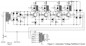
The project posted here is called an automatic voltage stabilizer circuit which solves almost all problems faced in the normally available stabilizer efficiently. With the help of the automatic voltage stabilizer circuit, we can keep the constant voltage at 230V when the voltage goes low as 170V and high as 250V automatically. The working strategy of the Automatic Voltage Stabilizer Circuit The working strategy of the circuit is very simple, this circuit energized one relay at a time from 170V AC upwards, and all relays and energized when 230V AC…
Read MoreOvervoltage Protection Circuit
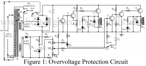
Multiple appliances have been born to ease human efforts. And in the same run, numerous protective circuits are designed to ensure a long lifespan of those devices. We have seen those circuits claiming to protect appliances like refrigerators and air-conditioners from voltage fluctuations and brown-outs. An overvoltage protection circuit has been presented here serving multi-purpose security; under-voltage protection, switch-on delay, and regulation. Description of Overvoltage Protection Circuit Do not get worried with the overvoltage protection circuit diagram, though it looks complex, the circuit comprises building blocks we have been familiar…
Read MoreLuggage Security System
Introduction to Luggage Security System Number of thefts and robbery has increased to a greater extent. Unemployment, poverty might have been the cause for this but still stealing others property is a serious crime. The only way to stop this is by alerting people themselves with proper security arrangements. Bus hijacking is what we heard commonly of, this is where the fear of crime lies. We have seen people stepping ahead for protection, they use chains, lock as security arrangements to secure their luggage. This might be a nice try,…
Read MoreHigh Current Regulator Circuit
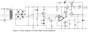
The high current regulator circuit can be delivering up to 3-amp load current continuously. The output voltage can be set in the range of 4V to 22V. Fine variation in the output voltage can also be done using a potentiometer VR3. The output current, ranging from 350mA to 3000mA can be varied by potentiometer VR1. Circuit Description of High Current Regulator Circuit The high current regulator circuit given here utilizes all the advantages of the operational amplifier LM3140 (IC1). It has very high input impedance, high gain, high CMRR, low…
Read MoreSpeech Filter Circuit
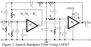
A speech filter circuit is a broadband filter and is also called a wide bandpass filter circuit because its bandwidth is restricted to the speech frequency. It can be formed by simple cascading high pass and low pass section and is generally the choice for simplicity of design and performance through such a circuit can be realized by a number of the possible circuits. The butter-worth filter is generally used in audio systems which are characterized by a maximally flat-flat filter. Description of Speech Filter Circuit: A speech filter using…
Read More24 Hour Digital Clock and Timer Circuit
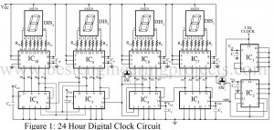
Electronic circuits are usually designed for a specific purpose, which means one circuit performs only one task, in general cases. This circuit here, “24-Hour Digital Clock and Timer Circuit” is a simple circuit with two different applications as reflected through the name 24-hour clock and a timer. The Circuit of a versatile 24-Hour Digital Clock and Timer Circuit is described below in detail. First, let’s go with some of its unique features. Various Other timer and clock circuits are posted in bestengineeringprojects.com Industrial Timer Circuit Countdown Timer using Arduino Programmable…
Read MoreDTMF Based Remote Control System
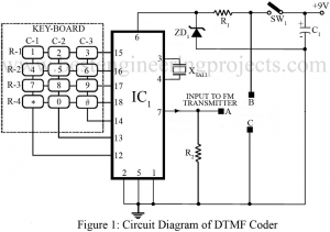
Different gadgets have been introduced to meet our requirements ranging from basic needs to classy needs of humans. With this development in recent years, day by day people has grown more sophisticated. Putting human comfort as a main concern, hereby we have presented a circuit to remotely control several electrical or electronic gadgets connected to it. The unique feature of the circuit DTMF-based remote control system in comparison to other remote control systems like IR remote control is that this circuit employs FM transmission and reception, for this reason, it…
Read MorePest Repeller Circuit
No matter how far we try to escape from pest’s trap or we attempt to clean the surrounding around us, we get eventually bothered being followed everywhere from kitchen to every corners of our house. Different pest repeller circuits have been developed claiming to escort people through this problem. However, pest repeller circuits thus built are found to have low power output resulting poor effectiveness. And, this error gives no solution to our trouble. With this point as our main concern, we have presented a powerful pest repeller circuit that…
Read MoreProximity Detector Circuit Using 555 timer IC
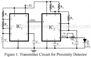
Entire project of proximity detector circuit is built with infrared transmitter, infrared receiver and 555 timer IC (such as using Seimens SFH50638 in TV sets). Proximity detector circuit, anyone can guess the operation performed by this circuit just with the name it is provided with. Infrared diode is the main soul of proximity detector circuit which is used in different equipment’s like burglar alarms, touch-free proximity switches for turning a light on, and solenoid controlled valves for operating a water tap. Description of Proximity Detector Circuit Using 555 timer IC Transmitter…
Read MoreRF Probe Circuit
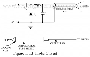
In order to measure the RMS voltage between two specific points, employing heavy and bulky electronic devices sounds unusual. And, therefore a small handy instrument can be used to avoid such situations where the voltage (i.e. RMS) between two points at any distance; large or small can be determined. For this reason, the instrument RF probe circuit has been proven of great help for home users as well as for communication equipment service/design labs. Description and Working of RF Probe Circuit RF probe circuit is just an instrument to measure, in…
Read More