For laboratory work, an accurate temperature deviation indicator is more effective than a sophisticated thermometer. The electronic device temperature deviation indicator using 741 can register a difference of 0.20C between the thermal sources and display it with the appropriate direction of variation. It can be used as a heater coil controller to maintain the equilibrium level.
Circuit Description of Temperature Deviation Indicator using op-amp 741
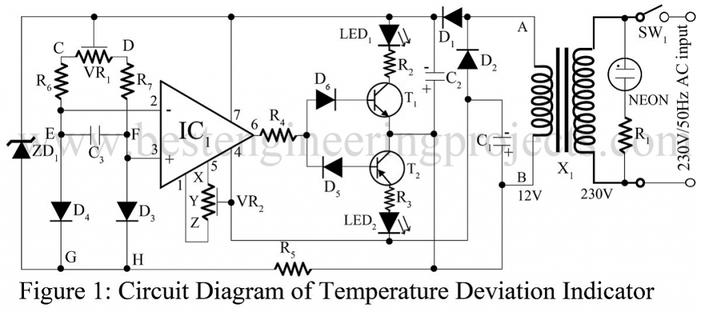
The circuit of temperature deviation indicator using op-amp 741 is simple and self-explanatory. Two silicon diodes (D3 and D4) complete a bridge network and act as sensor elements. These have a negative temperature coefficient (like thermisters) of approximately 2mV/0C. The difference in temperature-dependent voltage created by the sensor diode is fed to an operational amplifier IC (op-amp 741) which is connected as an open-loop differential amplifier or voltage comparator. The output of the op-amp (IC1) swings to positive or negative saturation according to the differential input. LED1 and LED2 thereupon display the temperature deviation.
Sensors can be kept immersed in liquid or gaseous-type thermal sources. Between a range of -500C to + 1500C, the device operates without considerable change in its efficiency. However, below the room temperature, its accuracy and sensitivity are found to be maximum. The circuit temperature deviation indicator is not influenced by identical changes at the sensors D3 and D4.
Leads of the sensor diodes can have a maximum length of two meters, twisted together or they may all be run together and rooted in a cable harness. Wires should be color-coded or labels may be used for identification. Leads are to be insulated properly to avoid possible short circuits.
For low-temperature operations, transistors serve as an effective sensor element. The emitter and base of transistor T1 (HL 100 or equivalent) should be connected together to form the anode of the sensor while the collector acts as the cathode. Its TO-5 package (Collector connected to the metal case) is a positive factor in the sensitivity of the unit.
Connection of Temperature Deviation Indicator to Heater
For heater control type operation, the combination LED1 –R2 and LED2 – R3 can be replaced by relays and transient suppressor diodes. Contact rating of the relay depends upon the power consumption of the heater coil. For a balanced temperature, the N/C (Normal-closed) contact type of the relay has to be selected. Hence the relay will be ‘off’ on the rise of temperature in any source.
Check out other temperature-controlled and indicator circuits posted in bestengineeringprojects.com
- ESP8266 Temperature Logger using PIC16F887
- Arduino Based Data Logger (Temperature)
- Temperature Controlled Fan using Arduino
- Wireless Temperature and Humidity Indicator for Fridge
- Dynamic Temperature Indicator and Controller Using Ardunio
PARTS LIST OF TEMPERATURE DEVIATION INDICATOR USING OP-AMP 741
| Resistor (all ¼-watt, ± 5% Carbon) |
| R1 = 470 KΩ
R2 = 220 Ω R3 = 200 KΩ R4 = 1 KΩ R5 = 2.2 KΩ R6, R7 = 22 KΩ VR1 = 2.2 KΩ (Linear preset) VR2 = 10 KΩ (Potentiometer) |
| Capacitors |
| C1, C2 = 1000 µF, 25V (electrolytic capacitor)
C3 = 0.01 µF (Ceramic Disc) |
| Semiconductors |
| IC1 = LM741 (Operational Amplifier)
T1 = HL 100 or SL 100 (Medium power NPN Silicon Transistor) T2 = HK 100 or SK 100 (Medium power NPN Silicon Transistor) D1, D2 = BY125 or BY126 or BY127 or 1N4001 (Rectifier Diode) D3, D4 = 1SM3 diode or equivalent (Power Diode) D5, D6 = 1N4001 (Rectifier Diode) ZD1 = HZ9.1 or equivalent zener diode |
| Miscellaneous |
| X1 = 230V to 12V (500mA) step-down transformer
NEON = Neon lamp supply indicator SW1 = SPST 250, 1A switch |
how the temperature is varied at the diode sensors in temperature deviation indicator circuit.
As we know that internal resistance of semiconductor is dependent of temperature. so if there is any variation of temperature the voltage is also on variation
May I know how can I read the temperature?
I mean from where I indicate the reading ?
As i listed above, the circuit “Temperature deviation indicator using op-amp 741” is not thermometer. it is used as temperature deviation indicator (i.e it indicate either temperature is increasing or decreasing by glowing led led1 and led2).
Could you please create a version of the circuit that uses DC input voltage?