Indoor games play a vital role in our busy schedule where we can’t spare time to refresh ourselves and enjoy game on the ground. In city areas, lack of playground can be a greater obstacle. The circuit electronic cricket project solves all problem, it is very interesting project not only for those who love cricket but for also those people who love to watch this game. The game electronic cricket can be played by anyone, even in their home by sitting on table or at the corner of a room,…
Read MoreGround Fault Interrupter
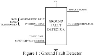
People are often injured badly and hospitalized with accidents due to the flow of current in the faulty circuits. To prevent this, a circuit ‘Ground fault interrupter’ has been developed. This circuit employs additional components along with a ground fault interrupter chip to produce a complete ground fault interrupter circuit. Check out more other electronics design related article posted in bestengineeringprojects.com The sole purpose of this particular circuit ground fault interrupter is to stop the flow of current in an electrical circuit when an electrical fault/short circuit, occurs. A sensing…
Read MoreWoofer Tweeter Crossover
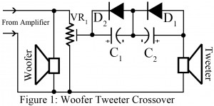
When using speakers, people must have faced quite a lot of problems due to failure of the speaker to produce smooth sound quality continuously. It is because speaker detects only identical frequency and does not give response to all frequency. Particular range of low frequencies is detected by the speaker and it ignores high frequencies. Woofer or tweeter is introduced as a solution to this issue. However, if the signal from amplifier is directly fed to woofer or tweeter, then it may not produce the actual sound. And, a crossover…
Read MoreCapacitor Tester cum Flasher
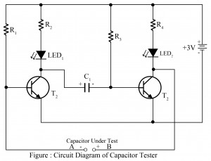
Capacitors are one of the basic components of any electronic project. Now, here we taught you, how to test capacitor whether is short, open or working. The simple circuit of the capacitor tester is built around two general-purpose NPN transistors. This circuit posted here is used to test capacitors up to 1000 µF. The capacitor to be tested is connected at points A and B as shown in the circuit diagram (positive terminal at point B where negative terminal at point A). Working of the circuit Capacitor Tester cum Flasher When…
Read MoreHigh Powered Strobe Light Using Arduino
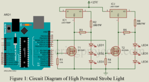
The project High Powered Strobe Light Using Arduino is the extended version of strobe light using arduino. Here, in this project we uses six high power Luxeon LED as used in previous project. This project show different strobe effect like flashing, fading, continuous illuminating etc. We can select any of this effect through serial monitor. Lets see the circuit diagram and how its work. Circuit Description of High Powered Strobe Light Using Arduino The circuit is shown in figure 1 and is designed around arduino uno board, N-Channel MOSFET, LM317…
Read MoreStrobe Light Using Arduino
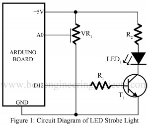
Here is one another project which is useful in our daily life using aduino. As we had already posted “High Brightness LED Strobe Using NE555” using array of 36 LEDs now here we use single high brightness Luxeon LED. The circuit of strobe light using arduino is shown in figure 1. The potentiometer VR1 is used to control the flashing rate of strobe light. PARTS LIST OF STROBE LIGHT USING ARDUINO Resistor (all ¼-watt, ± 5% Carbon) R1 = 270 Ω R1 = 4 Ω/1W VR1 = 100 KΩ Semiconductors…
Read MoreSound VU Meter Using Arduino
Different gadgets have been introduced to meet our requirements ranging from the basic needs to the classy needs of humans. With this development in recent years, people have grown more sophisticated day by day. Hereby we have presented a circuit sound VU meter using Arduino to display the volume of noise picked up by a microphone. Circuit Description of Sound VU Meter using Arduino The push-to-on switch SW1 is used to change the mode of the sound VU meter. In normal mode, the LEDs just flicker up and down with…
Read MoreLED Dice Using Arduino
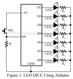
Here you will find the tutorial to build a simple LED dice using arduino. The software build will be reliable and perfect enough to implement it in a real working environment. This project is very helpful in to build a basic arduino system. Arduino technology is easy to use, efficient and reliable where it also allows dynamic and faster control. In this project we used random number generation technique. Every time you press the button, the LED’s roll for a while and glow a single LED. Figure 1 show the…
Read MoreDynamic Temperature Indicator and Controller Using Ardunio
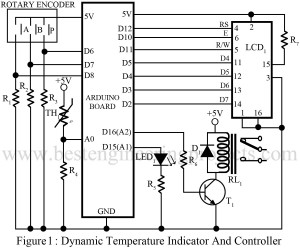
Here is a standalone Dynamic Temperature Indicator and Controller Using Ardunio that also controls the electric appliance according to temperature. The use of Arduino technology makes this closed-loop feedback control system efficient and reliable. Arduino allows dynamic and faster control. Here we used a rotary encoder and liquid crystal display for more users friendly. The sensed and set temperature values are simultaneously displayed on the LCD panel in centigrade which can be changed Kelvin in scale. Circuit Description of Dynamic Temperature Indicator and Controller Using Arduino The circuit is programmed…
Read MoreCountdown Timer Using Arduino
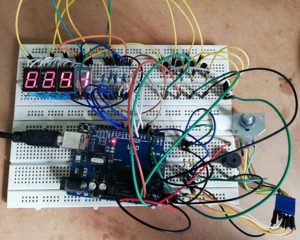
The circuit here Countdown timer using Arduino is a simple circuit with the facility of the timer, this circuit is designed for 50 minutes timer but you can change it according to your requirement. Electronic circuits are usually designed for a specific purpose, which means one circuit performs only one task, in general cases. When this circuit is used, the time at which it is selected can be stored electronically while being displayed simultaneously. Talking about the circuit components, it uses an Arduino board, 7-segment display, PNP transistor, and a…
Read More
