Arduino board is designed for working with digital signal or square wave signal. If we want to generate sine wave, we have to do little effort, because analog output from arduino is not true analog but a PWM output which turn board on and off very frequently. Here we use digital to analog converter to generate fine analog output. A digital to analog converter has a single output having number of digital input. PARTS LIST OF YUNE LAYER USING ARDUINO Resistor (all ¼-watt, ± 5% Carbon) R1 – R4, R8…
Read MoreInfrared Remote Controller Using Arduino
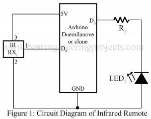
Here is projects called “Infrared Remote Controller Using Arduino” which allow you to control any type of electrical gadget using any infrared remote control. The project posted here records an infrared message from an existing remote control and give output as required. Here, we use EEPROM memory to store the infrared signal code so that we can use this remote even arduino board is disconnected. Circuit Description of Infrared Remote Controller Using Aruino:- The circuit of infrared remote controller is designed using an arduino board and a IR receiver module.…
Read MoreLED Chaser Circuit Using NE555
Various types of LED-based projects are already posted on bestengineeringprojects.com. Now, here is a simple project called LED chaser Circuit using NE555 in which 10 different LED is arranged in a column. The LED arranged in column glow from top to bottom, one at a time. Description of LED Chaser Circuit Using NE555 The circuit of the LED chaser is designed around a timer IC NE555 (IC1) and decade counter IC CD4017 (IC2). Here, IC1 is used in astable multivibrator mode which generates a clock pulse in a fixed interval…
Read MoreSurveillance Robot
Software Code:-
|
1 2 3 4 5 6 7 8 9 10 11 12 13 14 15 16 17 18 19 20 21 22 23 24 25 26 27 28 29 30 31 32 33 34 35 36 37 38 39 40 41 42 43 44 45 46 47 48 49 50 51 52 53 54 55 56 57 58 59 60 61 62 63 64 65 66 67 68 69 70 71 72 73 74 75 76 77 78 79 80 81 82 83 84 85 86 87 88 89 90 91 92 93 94 95 96 97 98 99 100 101 102 103 104 105 106 107 108 109 110 111 112 113 114 115 116 117 118 119 120 121 122 123 124 125 126 127 128 129 130 131 132 133 134 135 136 137 138 139 140 141 142 143 144 145 146 147 148 149 150 151 152 153 154 155 156 157 158 159 160 161 162 163 164 165 166 167 168 169 170 171 172 173 174 175 176 177 178 179 180 181 182 183 184 185 186 187 188 189 190 191 192 193 194 195 196 197 198 199 200 201 202 203 204 205 206 207 208 209 210 211 212 213 214 215 216 217 218 219 220 221 222 223 224 225 226 227 228 229 230 231 232 233 234 235 236 237 238 239 240 241 242 243 244 245 246 247 248 249 250 251 252 253 254 255 256 257 258 259 260 261 262 263 264 265 266 267 268 269 270 271 272 273 274 275 276 277 278 279 280 281 282 283 284 285 286 287 288 289 290 291 292 293 294 295 296 297 298 299 300 301 302 303 304 305 306 307 308 309 310 311 312 313 314 315 316 317 318 319 320 321 322 323 324 325 326 327 328 329 330 331 332 333 334 335 336 337 338 339 340 341 342 343 344 345 346 347 348 349 350 351 352 353 354 355 |
// Surveillance Robot #define HALT 0 #define CLOCKWISE 1 #define COUNTER_CLOCKWISE 2 int leftAPin = 7; int leftBPin = 6; int rightAPin = 5; int rightBPin = 4; int posPin = 14; int negPin = 15; int proxPin = 2; int pirPin = 3; int buzzPlusPin = 9; int buzzMinusPin = 8; float proxThreshold = 500; float alpha = 0.5; int pirThreshold = 10; int monitorDuration = 120; // seconds int alarmDuration = 10; // seconds void setup() { pinMode(leftAPin, OUTPUT); pinMode(leftBPin, OUTPUT); pinMode(rightAPin, OUTPUT); pinMode(rightBPin, OUTPUT); pinMode(pirPin, INPUT); digitalWrite(leftAPin, LOW); digitalWrite(leftBPin, LOW); digitalWrite(rightAPin, LOW); digitalWrite(rightBPin, LOW); pinMode(posPin, OUTPUT); pinMode(negPin, OUTPUT); pinMode(buzzPlusPin, OUTPUT); pinMode(buzzMinusPin, OUTPUT); digitalWrite(posPin, HIGH); digitalWrite(negPin, LOW); Serial.begin(9600); } void loop() { monitor(); moveToNewPlace(); delay(1000); } void monitor() { int alarmTimeout = 0; for (int i = 1; i < monitorDuration; i++) { int pirValue = analogRead(pirPin); if (pirValue > 10) { digitalWrite(buzzPlusPin, HIGH); alarmTimeout = alarmDuration; } if (alarmTimeout <= 0) { digitalWrite(buzzPlusPin, LOW); } alarmTimeout "”; delay(1000); } } void moveToNewPlace() { turnInRandomDirection(); forwardOrProximity(1500); } void turnInRandomDirection() { int duration = random(100, 3000); left(); delay(duration); halt(); } void forwardOrProximity(int duration) { int x = 0; forward(); static float lastProx = 0; float prox = 0; while (x < duration) { int rawProx = analogRead(proxPin); prox = alpha * rawProx + (1 - alpha) * lastProx; Serial.print(rawProx); Serial.print(" "); Serial.print(lastProx); Serial.print(" "); Serial.println(prox); lastProx = prox; if (prox > proxThreshold) { halt(); buzz(50); buzz(50); delay(100); back(); delay(700); halt(); return; } x += 10; delay(10); } } void forward() { setLeft(CLOCKWISE); setRight(CLOCKWISE); } void back() { setLeft(COUNTER_CLOCKWISE); setRight(COUNTER_CLOCKWISE); } void left() { setLeft(CLOCKWISE); setRight(COUNTER_CLOCKWISE); } void right() { setLeft(COUNTER_CLOCKWISE); setRight(CLOCKWISE); } void halt() { setLeft(HALT); setRight(HALT); } void setLeft(int rotation) { if (rotation == HALT) { digitalWrite(leftAPin, LOW); digitalWrite(leftBPin, LOW); } else if (rotation == CLOCKWISE) { digitalWrite(leftAPin, HIGH); digitalWrite(leftBPin, LOW); } else if (rotation == COUNTER_CLOCKWISE) { digitalWrite(leftAPin, LOW); digitalWrite(leftBPin, HIGH); } } void setRight(int rotation) { if (rotation == HALT) { digitalWrite(rightAPin, LOW); digitalWrite(rightBPin, LOW); } else if (rotation == CLOCKWISE) { digitalWrite(rightAPin, HIGH); digitalWrite(rightBPin, LOW); } else if (rotation == COUNTER_CLOCKWISE) { digitalWrite(rightAPin, LOW); digitalWrite(rightBPin, HIGH); } } void buzz(int duration) { digitalWrite(buzzPlusPin, HIGH); delay(duration); digitalWrite(buzzPlusPin, LOW); delay(duration); } |
Read More
Hypnotizer Using Arduino
Hypnotizer is device which is used to control mind and is one of the favorite things of us. Here is a project called hypnotizer using arduino shown in figure 1, which control the motor and also rotate it into clock wise and anti close wise direction. A spiral disk shown in figure 2, attached to a motor and rotates as motor rotates to mesmerize the unfortunate victims. Project Description of Hypnotizer Using Arduino The Project Hypnotizer is divided into two sections: Hardware Section and Software Section Hardware Section:– The circuit…
Read MoreSound Operated Light and Alarm Circuit
Various types of security-based projects are already available on bestengineeringprojects.com. Now here is sound operated light and alarm that is used as an intruder alarm, activated when any sound is detected (like the opening of doors, knocking, or door opening) and starts flashing with a sound that alerts you of an intruder. After the second sound pulse is turned off. Circuit Description of Sound Operated Light and Alarm The circuit of sound-operated light and alarm is designed using a pair of timer IC (NE555), a dual JK flip flop IC…
Read MoreLED Running Light Circuit
Various types of running or disco lights are already available on bestengineeringprojects.com. Now here very simple LED Running light circuit using two transistors. Circuit Description of LED Running Light Circuit: The entire circuit of LED running light is designed using two general purpose NPN transistors. The design and working of this circuit are very simple and straightforward. Both of these transistors are configured in astable multivibrator mode. Initially when no power supply is connected, both the transistor drives to cut off region and none of this LED glow. But when…
Read MoreNocturnal Screamer Circuit using CD4099
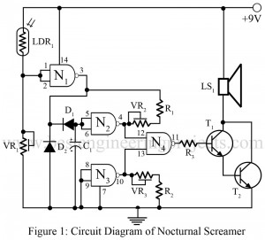
Here is simple electronic fun project which is designed using digital gate IC (CD4092BE) called Nocturnal Screamer Circuit using CD4099. In absence of light it produce loud scramming sound but when light is switched on, sound will disappeared. In this way we can used this project for fun. Circuit Description of Nocturnal Screamer Circuit using CD4099 The circuit of nocturnal screamer is designed using quad two input NAND gate IC (CD4099BE) is shown in figure 1. Here LDR is used as sensor which detects light and change its internal resistance…
Read MoreNi-Cd Battery Charger
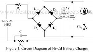
These days many of electrical appliances (watch, RC car, radio etc) use Ni-Cd battery. Here is a simple circuit of Ni-Cd battery charger in the series of easy electronics projects. Circuit Description and working principle of Ni-Cd Battery Charger Basically Circuit of Ni-Cd battery charger is rectifier. The input from AC mains is directly given to the circuit through resistors R1 and R2, where resistor R1 is used to limit the surge current and resistor R2 with capacitor C1 is used to limit the leakage charge current. The output from…
Read MoreAural Metronome Circuit
A metronome is a device which produces regular beats and is measured in beats per minute. Here is project called aural metronome circuit which produce fixed sound (Tick – Tick) like quartz watch. The stability of pulse can be adjusted from 40 to 400 ticks per minutes using preset VR1. Circuit Diagram of Aural Metronome Circuit The circuit of aural metronome is designed using a CMOS quad NAND gate IC (CD4011), out of which we uses two NAND gates only. Variable resistor VR1 is used to control the rate of…
Read More


