Various types of running or disco lights are already available on bestengineeringprojects.com. Now here very simple LED Running light circuit using two transistors.
Circuit Description of LED Running Light Circuit:
The entire circuit of LED running light is designed using two general purpose NPN transistors. The design and working of this circuit are very simple and straightforward. Both of these transistors are configured in astable multivibrator mode.
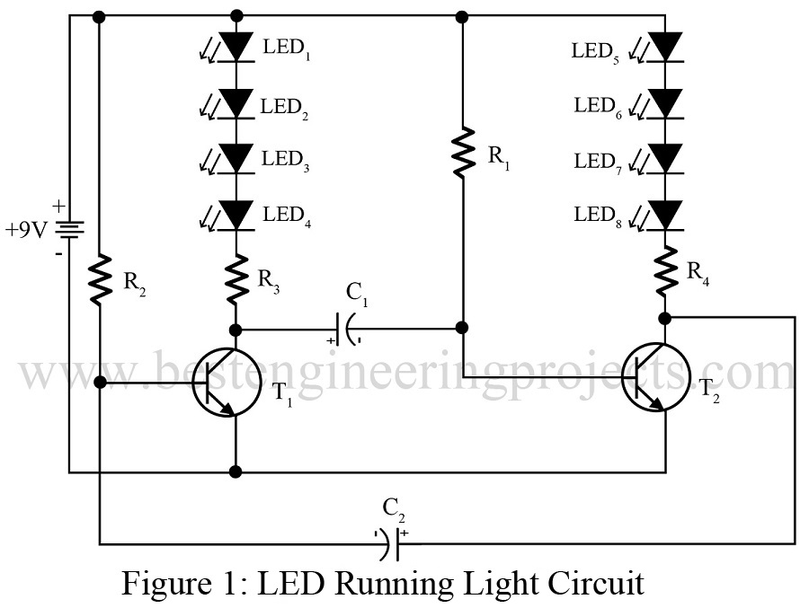
Initially when no power supply is connected, both the transistor drives to cut off region and none of this LED glow. But when the power supply is connected transistor T1 starts conducting and transistor T2 still drives to the cut-off region, LEDs connected to transistor T1 start glowing. After some time transistor T1 drives to the cut-off region and transistor, T2 starts conduction as a result LEDs connected to transistor T2 start glowing. This entire process repeats after some time.
Check out other LED Project posted on bestengineeringprojects.com
- LED Matrix Display using Arduino
- LED Cube 4x4x4 Circuit using AT89C2051
- DIY Light Detector Circuit using LED
- Sound Level Meter Circuit
PARTS LIST OF SIMPLE LED RUNNING LIGHT CIRCUIT
| Resistor (all ¼-watt, ± 5% Carbon) |
| R1, R2 = 56 KΩ
R3, R4 = 150 Ω |
| Capacitors |
| C1, C2 = 10 µF, 12V (Electrolytic Capacitor) |
| Semiconductors |
| T1, T2 = BC147 (General Purpose NPN Silicon Transistor)
LED1 – LED8 = Different color LEDs |