People are often injured badly and hospitalized with accidents due to the flow of current in the faulty circuits. To prevent this, a circuit ‘Ground fault interrupter’ has been developed. This circuit employs additional components along with a ground fault interrupter chip to produce a complete ground fault interrupter circuit.
Check out more other electronics design related article posted in bestengineeringprojects.com
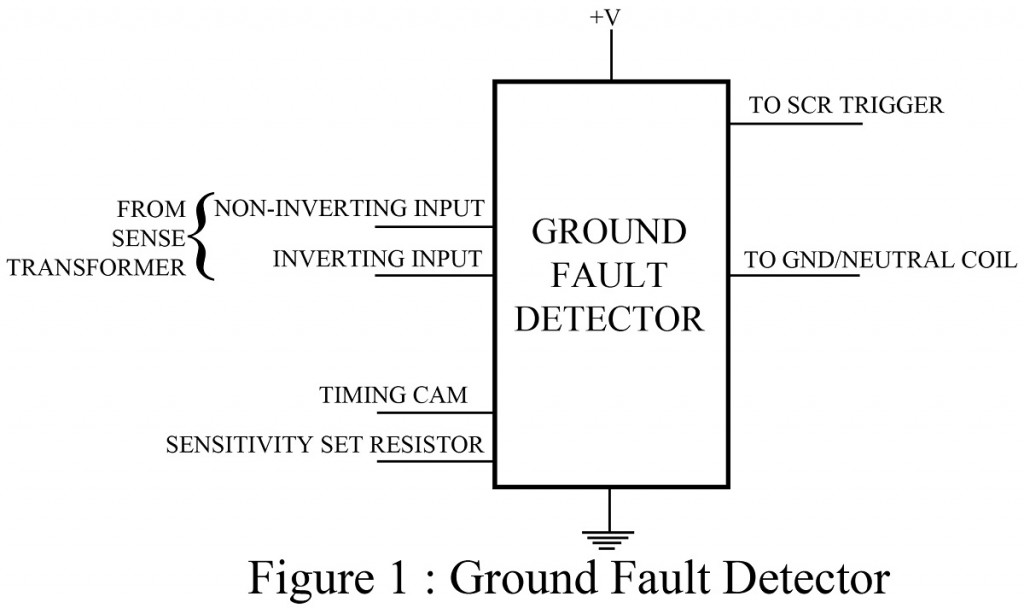
The sole purpose of this particular circuit ground fault interrupter is to stop the flow of current in an electrical circuit when an electrical fault/short circuit, occurs. A sensing transformer senses the normal current flow through electrical power lines and this value is fed to the chip as input. At time of fault, the sensed current rises above a preset limit and then the chip immediately produces a triggering pulse which is used to fire an SCR. As a result, the SCR opens a power line circuit breaker which ultimately stops the flow of current in the faulty path. Sometimes line noise can also increase the current level. In order to avoid false alarm due to this situation, an external timing capacitor is used by the chip.
Basic key parameters of Ground Fault Interrupter are described in points below:
- Normal fault current sensitivity: – A normal fault occurs as the result of an accidental current path between the load hot line and ground. The current sensitivity is the amount of current above nominal levels that will cause the chip to respond. Typical sensitivity value is 5mA.
- Normal fault trip time: – It is the amount of time it will take for a chip to respond to a fault condition. Typical trip time is 18 msec.
- Output drive current: – This is the amount of current supplied to trigger the SCR upon detection of a fault, 1mA is typical.
Applications of Ground Fault Interrupter
This chip is used to develop ground fault interrupter circuits.