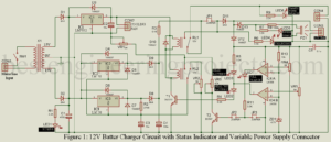
There are lots of 12V Lead Acid Battery Charger Circuit available over the internet but does not include a battery status indicator. If you wish to know the status of the battery like dead, charged, or charging you need an extra circuit. In order to solve these problems, we combined three different circuits and hence do three different dedicated jobs like charging the battery, indicating the status of the battery, and also have a dedicated port for variable power supply connector of bench power supply in case you need. This…
Read MoreDIY Arduino Controlled Guitar Pedal
DIY Arduino Controlled Guitar Pedal: Here in this article, you will learn how to design a programmable pedal for guitar using an Arduino UNO board. For understanding this project, you do not need deep knowledge of programming, digital signal processing, and electronic hardware. All you need is a little familiar with soldering and C programming. We have described the project in a very detailed and simple manner. This DIY Arduino Controller Guitar pedal is designed for hobbyists and those who took interest in music and guitar. Features of DIY Arduino…
Read MoreThree Phase Power Surge Protector Circuit
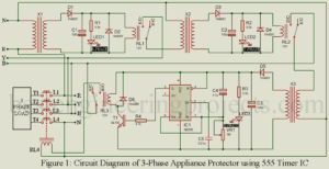
Three are two types of electrical/electronics appliances based on the main supply it requires. Generally, heavy electrical equipment requires a three-phase main supply for working. Three-phase mains supply has three different phases each are placed at 1200 angle with each other. In this post, you will learn how to design a three-phase power surge protector circuit using timer IC 555. A three-phase electrical appliance is expensive and requires all phase supplies, if voltage fluctuates or fails in any phase operation of the appliance may malfunction or become dead. In order…
Read MoreBest Audio Amplifier Circuit
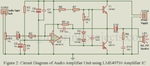
Electronics hobbyist love to design their own gadget which cam be used in our daily life. In the website Best Engineering Projects, we had published 100’s of such project which make life easy and sophisticated. In this post you will learn how to design your own Best audio amplifier circuit with premium specification. Specification of Best Audio Amplifier Circuits Output impedance of the circuit: 0.01Ω Frequency response i.e. working frequency: 20 Hz to 40 KHz Total harmonic distortion: 1.2% at 3W. Load or Speaker at output: 3Ω to 8Ω Description…
Read MoreFour Channel Audio Amplifier Circuit
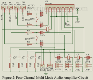
Single channel audio amplifier is readily available over internet, generally we combine multiple single channel amplifier in order to built multiple channel amplifier. But here in this post you will learn how to design four channel audio amplifier circuit using TDA1554Q IC. This type of circuit is very useful in sound lab, school, office etc. where we need multiple into and multiple output. Specification and Advantage of Four Channel Audio Amplifier Circuit Four input and four output port At load it provides 11W of power and at load it provide 6W…
Read MoreZener Breakdown and Avalanche Breakdown
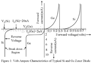
Figure 1 gives the volt-ampere characteristic of a PN diode including the breakdown region. Thus, when a PN diode is highly reverse biased, the junction may breakdown i.e. it presents extremely small resistance with the result that the current increases abruptly at an almost constant voltage. This current may be limited only by placing a suitable resistor in the external circuit. However, the breakdown is not permanent. The diode returns to its normal condition when this large reverse bias is removed. The breakdown of diode may be of two types:…
Read MoreTransition Capacitance and Diffusion Capacitance of Diode
Transition Capacitance CT of Diode (Space Charge Capacitance) With the increase of the magnitude of reverse bias, majority carriers move away from the junction i.e. the width W of the depletion layer increases. This uncovered immobile charge on the two sides of the junction constitute a capacitor of incremental capacitance CT is given by, ……..(1) Where dQ is the increase in the charge resulting from an increase dV in voltage. Hence, a voltage change dV in the time interval dt will result in a current i was given by,…
Read MoreVolt Ampere Characteristic of a PN Diode
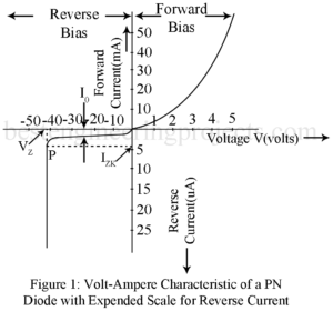
What is Volt Ampere Characteristic of PN Diode? Current I in a PN diode in related to the junction voltage VV by the relation given by equation, ………..(1) Figure 1 gives the typical volt-ampere characteristic for a PN diode plotting above equation. With forward bias, the forward current remains essentially zero until the so called Cutin voltage VV of t diode is reached. This cutin voltage is defined as the voltage below which the forward current is less than 1% of the maximum rated current of the diode. This…
Read MoreForward and Reverse Biased PN Diode
Here in this article we are going to discuss about forward and reverse biased PN diode. We had also derive the equation and solve a numerical example. At first let’s see the reverse biased pn diode. Reverse Biased PN Diode Figure 1 shows a PN diode with reverse bias i.e. with negative terminal of the battery connected to the P-side of the diode and the positive terminal to the N-side. With the polarity of connection, holes in the P-region and the electrons in the N-region move away from the junction…
Read MoreOpen Circuit PN Diode
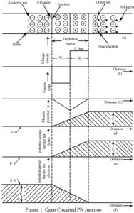
What is Open Circuit PN Diode? Figure 1(a) shows an open circuited pn diode with acceptor impurity density NA in the p-region and donor impurity density ND in the n-region. We assume that each acceptor atom has ionized resulting in one immobile negatively charged acceptor ion and one mobile hole. Similarly, each donor atom has ionized resulting in one immobile positively charged donor ion and one mobile electron. In Figure 1(a) the immobile acceptor ion is indicated by a minus sign enclosed within a circle while immobile donor ion is…
Read More