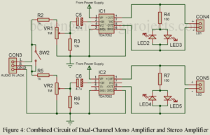
Stereo Amplifier Circuit Diagram we are going to design here is basically the combination of two mono audio amplifier. Portable and good audio amplifier is still a major concern to many electronic hobbyists and professional. People are still searching for good portable and battery-operated stereo amplifier. So, here in this article you will learn about designing of stereo amplifier using two audio amplifier IC. This stereo amplifier works with low voltage battery (4.5V, 6V) or even with a USB interface (+5V). In order to achieve above specification, we most design…
Read MoreTypes of PN Junction Diode
In this Tutorial we are describing PN diode and types of PN Junction Diode. What is PN Junction Diode? A PN junction or P-N diode consists of a semiconductor having two regions, a p-region and n-region with a junction in between. The junction region or the transition region where the nature of the semiconductor material changes from p-type to n-type is usually very thin, typically 10-6 to 10-4 cm wide depending on the method of concentration. What are the types of PN Junction Diode? Depending on the method of construction,…
Read More10 Watt Audio Amplifier Circuit with Volume Control
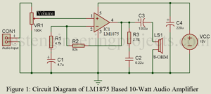
An amplifier that only amplify audio frequency range (typically 20Hz to 20K Hz) and attenuates all other range frequency range is called an audio amplifier. So, here in this post you will learn about power amplifier IC and at last we will design a 10-Watt Audio Amplifier Circuit with Volume Control using power amplifier IC with the features of volume control. We had already posted various amplifier circuit you may like. 7-Watt Audio Amplifier using TBA810 10-Watt Audio Amplifier using Transistor 20-Watt Audio Amplifier using TDA2020 20-Watt Audio Amplifier using…
Read MoreArduino Controlled 12V battery charger circuit
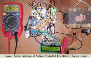
Arduino is an open-source that is designed for artists or for those who do not have an electronic background. Here, in this article, we are going to show you the method of making a battery charger circuit controlled using an Arduino uno board. The project Arduino Controlled 12V battery charger circuit is an advanced version of the previous posted project “12V, 7Ah Smart Battery Charger with PCB Diagram”. This charger also has the features of bulk stage charging and float stage charging as in the previous circuit. Silent features of…
Read MoreCommon Emitter Configuration of PNP Transistor
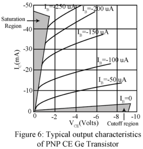
In the common-emitter configuration of PNP, the transistor emitter is the terminal common to both the input side and output side. The signal to be amplified is applied between base and emitter forming the input circuit while the amplified output voltage is developed across load impedance in the collector-to-emitter forming the output circuit. Figure 1 gives the basic circuit of a CE amplifier using load resistor RC. The Large Signal Current Gain | Common Emitter Configuration of PNP Transistor In a CB transistor, IE forms the input current while IC is…
Read MoreInput and Output Characteristic Curves of CB Transistor
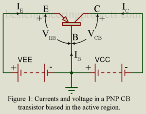
Here in this article we will going to discuss about characteristic curves of CB transistor like static input and static output characteristic curve of CB transistor (Common Base). Characteristic Curves of Transistor in Common Base Configuration Figure 1 shows a PNP transistor connected in Common Base (CB) configuration. Base is the terminal common to the input side and the output side and this terminal has been grounded. Then we are left with two voltage variables namely VEB and VCB. Further the current IB is ignored since it is nothing but…
Read MoreInterfacing of Unipolar and Bipolar Stepper Motor with Arduino
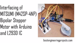
In this article we are going to interface unipolar and bipolar stepper motor and arduino using ULN2003 and L293D. The motor we are going to interface are MITSUMI M42SP-4NP stepping motor and 28BYJ-48 steeper motor Introduction Stepping motor | Interfacing of Unipolar and Bipolar Stepper Motor with Arduino An electric motor that rotates in a series of equal steps, each step controlled by a digital input signal, stepping motor are used in most electromechanical devices. Also called stepper motor. A stepper motor is an incremental motion machine i.e. the motor which…
Read MoreAmplifying Action of Transistor
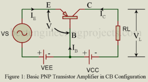
In this article you will learn about emitter efficiency, base transport factor, The early effect, dynamic emitter resistance and amplifier action of transistor. What do you mean by amplifying action of transistor? A transistor may serve various functions but basically it is used to amplify an electrical signal. Figure 1 gives the basic circuit of a PNP transistor amplifier in common base (CB) configuration. However, we may use an NPN transistor and get the same results. In figure 1, the transistor is biased for active region operation i.e. JE is…
Read MoreOptical Fiber Troubleshooting
Today optical fiber is the infrastructure of many communication hubs. Fiber carries billions of telephone calls a day. Optical fiber makes up the backbone structure of many local area networks currently in use. In this section, we will look at planning an optical fiber installation and maintaining it once it is in place. Remember, the diode lasers (DLs) can emit radiation with a far higher energy density than sunlight, and even though you can’t see the radiation, it can easily cause blindness by retinal heating. You should always wear eye…
Read MoreCurrent Components in a Transistor in Active Region Operation
Figure 1 shows the various current components in a pnp transistor operating in the active region. The entire emitter current IE consist of two parts (i) hole current IpE carried by holes diffusing across JE from p-type emitter to n-type base and (ii) electron current InE carried by electrons diffusion across JE from n-type base to p-type emitter. The ratio equals where and are respectively the conductivity of the p-type emitter region and n-type base region. Typically > . Hence in a pnp transistor, IpE>>Inr and hence we may neglect…
Read More