Single channel audio amplifier is readily available over internet, generally we combine multiple single channel amplifier in order to built multiple channel amplifier. But here in this post you will learn how to design four channel audio amplifier circuit using TDA1554Q IC. This type of circuit is very useful in sound lab, school, office etc. where we need multiple into and multiple output.
Specification and Advantage of Four Channel Audio Amplifier Circuit
- Four input and four output port
- At
 load it provides 11W of power and at load it provide 6W of power.
 - Can be used for and load.
- Dedicated controlled switch for different mode.
- Two dedicated mode: Single channel and bridge-tied load (BTL)
- Gain: In single channel mode 20 dB, In bridge-tied load mode 26 dB.
 load it provides 11W of power and at
  load it provide 6W of power.
 and
and  load.
load.Checkout other amplifier circuit posted in bestengineeringprojects.com
- Stereo Amplifier Circuit Diagram
- 10 Watt Audio Amplifier Circuit with Volume Control
- Audio Distribution Amplifier Circuit using LM324
- 20 Watt Audio Amplifier using TDA2003
- Audio Amplifier Circuit Using 555 IC
Description and Working of Four Channel Audio Amplifier Circuit
The circuit of four channel audio amplifier is divided into two section i.e. power supply section and amplifier section.
Power supply section | Four Channel Audio Amplifier Circuit
AC mains input is given to primary winding of transformer through switch SW3. A fuse of 2.5A is connected for protection. A snubber circuit is also connected to primary winding as shown in circuit diagram, it neutralizes the induced voltage at primary winding when switch SW3 open and hence protect the winding.
Transformer X1 step down the input AC (220V) to 12V AC and is given to bridge rectifier input. The rectifier is designed using four schottky diode, you can also use other diode with low voltage drop. The ration of diode must not be less then 10A because current rating of transformer is 6A or 8A.
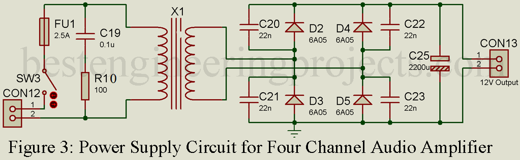
Ceramic capacitor is connected in parallel to rectifier diode as shown in circuit diagram. Generally, the transformer used in power supply have leakage inductance and parasitic capacitance. When we switch off the circuit, diode used in rectifier form a oscillatory circuit which oscillate at high frequency. This high frequency transfer to the rest of the circuit. In order to prevent this oscillator a capacitator is connected to parallel to each diode of rectifier as shown in circuit diagram. This capacitor damp the high frequency and drop it to low frequency.
One electrolytic capacitor is connected to output of rectifier for regulation purpose. The output of this rectifier is connected to power supply arrangement circuit.
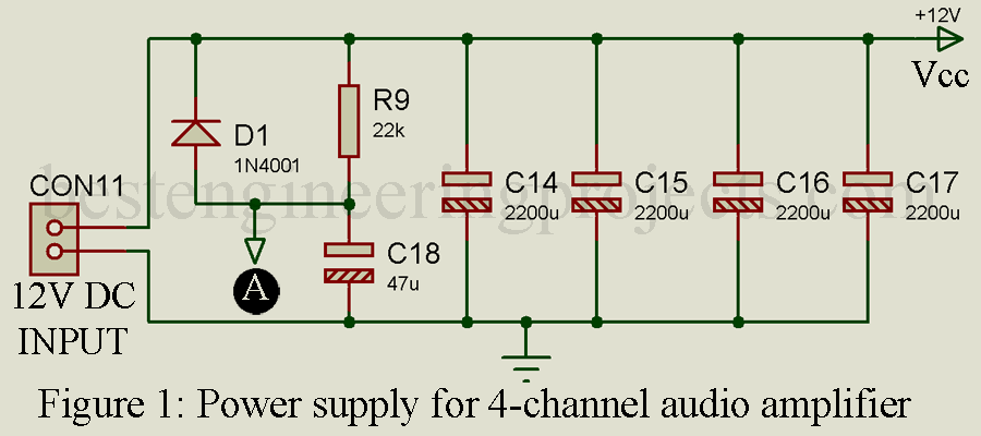
This 12V DC input is connected to capacitor bank and a RC snubber circuit. A diode is also connected parallel to resistor R9. Point A is connected to pin 14 if IC1. +12V output pin is connected to Vcc pin of amplifier circuit where ground of all circuit must be connected together.
Amplifier Section | Four Channel Audio Amplifier Circuit
The amplifier circuit is designed around power amplifier IC TDA1554Q. TDA1554Q IC is basically a class B output amplifier designed in single in line package. The input from different pre-amplifier or sound source like laptop, mobile etc. is given to connector CON1 to CON4 as shown in circuit below. According to data sheet of TDA1554Q input resistance is about 60k-ohm and this resistance can be reduced if we use multiple input pins in parallel. If two input is used, input resistance is half where as if four input is used in parallel input resistance is reduced by four times.
The capacitor connected between IC and audio input connector is enough to supply sound even at low-frequency range.
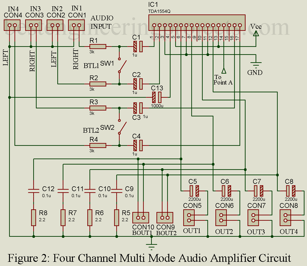
The two switch SW1 and SW2 is used to change the mode of operation i.e. single channel mode and Bridge tied load (BTL) mode. When switch SW1 and SW2 is closed the output is available at connector CON9 and CON10. At this mode the output power is about 22W on 4-ohm speaker and the gain is about 26dB.
PARTS LIST OF FOUR CHANNEL AUDIO AMPLIFIER CIRCUIT
| Resistor (all ¼-watt, ± 5% Carbon Unless Stated Otherwise) |
| R1 – R4 = 3 KΩ
R5 – R8 = 2.2 Ω R9 = 22 KΩ R10 = 100 Ω |
| Capacitor |
| C1 – C4 = 1 µF, 50V (Electrolytic Capacitor)
C5 – C8 = 2200 µF, 25V (Electrolytic Capacitor) C9 – C12 = 0.1 µF (Ceramic Disc) C13 = 1000 µF, 25V (Electrolytic Capacitor) C14 – C17, C24 = 2200 µF, 35V (Electrolytic Capacitor) C18 = 47 µF, 35V (Electrolytic Capacitor) C19 = 0.1 µF, 440V (Polyester Capacitor) C20 – C23 = 22 nF (Ceramic Disc) |
| Semiconductors |
| IC1 TDA1554Q (Audio Power Amplifier)
D1 = 1N4001 (Rectifier Diode) D2 – D6 = 6A05 (Rectifier Diode) |
| Miscellaneous |
| X1 = 230V AC Primary to 12V, 6A secondary transformer
FU1 = 2.5A Fuse CON1 – CON4 = 3.5mm stereo female panel-mount connector CON5 – CON10 = 2-way panel mount spring loaded speaker connector CON11 – CON13 = 2-pin connector terminal SW1 – SW3 = ON/OFF Toggle Switch |