Electronics hobbyist love to design their own gadget which cam be used in our daily life. In the website Best Engineering Projects, we had published 100’s of such project which make life easy and sophisticated. In this post you will learn how to design your own Best audio amplifier circuit with premium specification.
Specification of Best Audio Amplifier Circuits
- Output impedance of the circuit: 0.01Ω
- Frequency response i.e. working frequency: 20 Hz to 40 KHz
- Total harmonic distortion: 1.2% at 3W.
- Load or Speaker at output: 3Ω to 8Ω
Description of Best Audio Amplifier Circuit
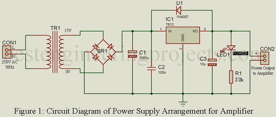
The circuit of audio amplifier need separate power supply unit thus, we are also going to show the power supply circuit and designing method.
Power Supply Unit | Best Audio Amplifier Circuit
Power supply unit is designed around step-down transformer, rectifier and series voltage regulator. Mains line input is given to primary winding of the transformer which step-down the voltage to 15V AC. This 15V AC is given to input of bridge rectifier BR1 and pulsating DC is obtained from output of rectifier. This pulsating DC is filtered using 1000 µF electrolytic capacitor (C1) and is given to the input of the series linear voltage regulator IC LM7812 (IC1). DC output available at pin 3 of IC1 is filtered by capacitor C3.
One diode 1N4007 (D1) is connected across the output pin (pin 3) to input pin (pin 2) of IC1 as shown in circuit diagram of power supply unit in order to protect the IC from reverse voltage. A LED is also connected with series current limiting resistor in order to indicate the power supply whereas resistor protect the diode from over voltage and current. Pure 12V DC is available at connector CON2.
Audio Amplifier Section | Best Audio Amplifier Circuit
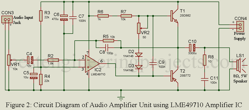
The amplifier section is designed around operational amplifier IC LME49710 (IC2). Input audio is given to inverting terminal of IC2 (pin 2) through variable resistor VR1 and electrolytic capacitor C4. Variable resistor VR1 is used to control the level of volume and capacitor C4 block the DC signal. A voltage divider network designed using resistor R3 and R4 is connected to non-inverting terminal in order to supply Vcc/2 voltage i.e. 6V to non-inverting terminal (pin 3). Capacitor C5 is used as bypass capacitor.
Two capacitors, one electrolytic capacitor (C6) and one ceramic capacitor (C7) connected in parallel used as de-coupler i.e. reduce the level of noise. Electrolytic capacitor C6 reduce the low frequency noise and min-frequency noise available in power supply, whereas ceramic capacitor reduces high frequency noise available in power supply lines. Gain of the amplifier is set by two resistors i.e. R2 and R5, where bandwidth of the amplifier is set by resistor R5 and capacitor C8.
Bias Current is set by two resistors R6 and R7 which is further adjusted by variable resistor VR2. Two diodes D2 and D3 do the job of multiplier. This bias current set by these resistive elements solves the problem of turn on base emitter drop of transistors T1 and T2, this current is also used to keep the transistors T1 and T2 active in-order to produce the output power when either load is connected or not.
Transistor T1 and T2 is used to drive the loudspeaker capacitor C10 is used here to block the DC signal. One RC network formed using resistor R8 and capacitor C11 is connected across the loudspeaker LS1. This network reduces the high frequency noise available at loudspeaker by forming a low-impedance path.
Adjustment of the Circuit | Best Audio Amplifier Circuit
- Connect all the component as shown in circuit diagram.
- Audio input connector (CON3) and variable resistor VR1 fit on the front panel of box.
- Variable resistor VR2 should be adjusted to about 11Ω.
- Enclosure the complete circuit in small box and connect the primary winding to mains supply.
PARTS LIST OF BEST AUDIO AMPLIFIER CIRCUIT
| Resistor (all ¼-watt, ± 5% Carbon Unless Stated Otherwise) |
| R1 = 2.2 KΩ
R2 = 1.8 KΩ R3, R4 = 22 KΩ R5, R7 = 10 KΩ R6 = 1 KΩ R8 = 10 Ω VR1 = 10 KΩ VR2 = 50 Ω |
| Capacitors |
| C1 = 1000 µF, 35V (Electrolytic Capacitor)
C2, C7, C9, C11 = 100 nF (Ceramic Disc) C3 – C5 = 10 µF, 25V (Electrolytic Capacitor) C6 = 470 µF, 25V (Electrolytic Capacitor) C8 = 100 pF (Ceramic Disc) C10 = 3300 µF, 25V (Electrolytic Capacitor) |
| Semiconductors |
| IC1 = LM7812 (12V Series Fixed Voltage Regulator)
IC2 = LME49710 (Operational Amplifier) T1 = 2SD882 (NPN Transistor) T2 = 2SB772 (PNP Transistor) D1 = 1N4007 (Rectifier Diode) D2, D3 = 1N4148 (Signal Diode) BR1 = DB107 (Bridge Rectifier) LED1 = 5mm any color LED |
| Miscellaneous |
| CON1 = Two pin male AC plug
CON2, CON4 = 2 pin connector CON3 = Audio input connector LS1 = 8 Ω, 5W Loudspeaker X1 = 230V, AC primary to 15V 1A secondary transformer |


it is fine if i change vr2 to 10ohm resistor?