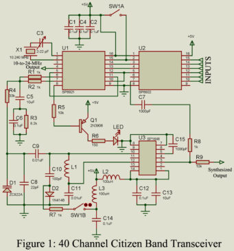
The availability of low-cost PLL and programmable divider ICs has led to the use of synthesizers in virtually all channelized transceivers. This is true even for the very low-cost systems used on the 40-channel citizen band transceiver. The circuit of the 40 Channel Citizen Band Transceiver is shown in Fig. 1 allows all necessary frequencies for a CB transceiver to be generated by using a single-crystal oscillator. The 40 channels are spaced at 10-kHz intervals (with some gaps) between 26.965 and 27.405 MHz. Local oscillator frequencies for the reception of…
Read MoreSimple White Noise Generator Circuit
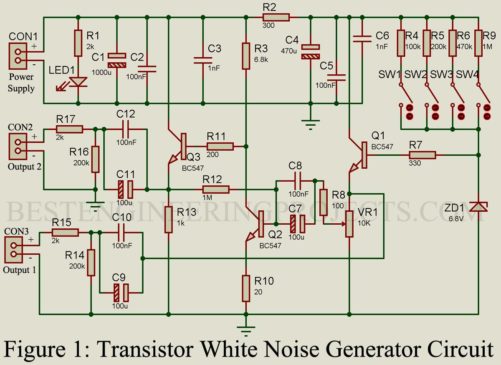
A signal which contains almost all frequencies is called white noise. In an audio system white noise contains only audible frequency. The white noise of the electrical system is analogous to white light from optics, where white light contains all frequencies or colors. White noise is mostly used in the testing audio equipment like pre-amplifier, power amplifiers, filters, etc. Check out the article on Electrical noise | Types of Electrical Noise. So, today in this article we are going to describe a simple white noise generator circuit. This circuit can…
Read MoreHow to Arduino Thermocouple Interface
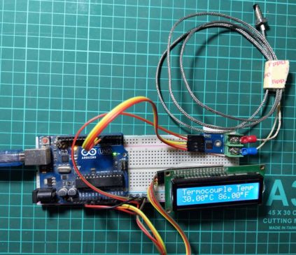
How to Arduino Thermocouple Interface: In this article, you will learn about interfacing K-type thermocouples and display temperature in Celsius and Fahrenheit on I2C LCD. Introduction of Thermocouple A thermocouple consists of a pair of dissimilar metal wires joined together at one end, called a sensing junction, and terminated at the other end, called the reference junction which is maintained at a known constant temperature called the reference temperature. When the sensing junction and the reference junction are at different temperatures, a potential difference gets produced which causes a current…
Read MoreWorking of LC Oscillator
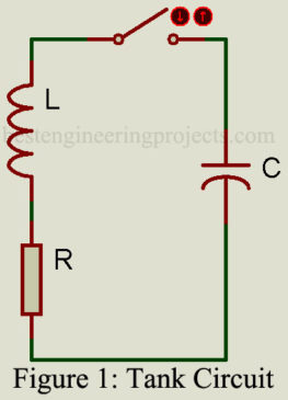
Working of LC Oscillator: The effect of charging the capacitor in Fig. 1 to some voltage potential and then closing the switch results in the waveform shown in Fig. 1. The switch closure starts a current flow as the capacitor begins to discharge through the inductor. The inductor, which resists a change in current flow, causes a gradual sinusoidal current buildup that reaches the maximum when the capacitor is fully discharged. At this point, the potential energy is zero, but since the current flow is maximum, the magnetic field energy…
Read MoreIntroduction and Advantages of Optical Communications
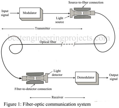
In the article Introduction and Advantages of Optical Communications, we will discuss optical communications and their advantages. Introduction of Optical Communication: Recent advances in the development and manufacture of fiber-optic systems have made them the latest frontier in the field of communications. They are being used for both military and commercial data links and have replaced a lot of copper wire. Their use in telecommunications is extensive. They are also expected to take over much of the long-distance communication traffic now handled by satellite links. A fiber-optic communications system is…
Read MoreElectrical Noise Measurement Technique
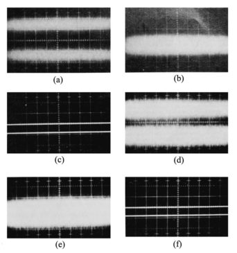
Electrical noise measurement has become a very sophisticated process. Specialty electrical/electronics noise measuring instruments that offer many computer-controlled functions are available for thousands of dollars. If you become involved with a large number of measurements, you will become familiar with some of these instruments. In this section, we look at some general methods of noise measurement that can be accomplished with relatively standard laboratory instrumentation. A simple and reliable method of noise measurement is the case where the signal is equal to the noise. At some convenient point in the…
Read MoreNoise Designation and Calculation
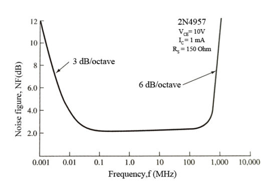
In the topic “Noise Designation and Calculation” we will discuss the various topics with proper mathematical equations and examples. The topic we are going to discuss are: Signal to noise ratio Noise Figure Resistor combination effect Reactance Noise effect Noise due to amplifier in a cascade Equivalent noise temperature Equivalent noise resistance Signal-to-Noise Ratio We have thus far dealt with different types of electrical noise without showing how to deal with noise in a practical way. The most fundamental relationship used is known as the signal-to-noise ratio (S/N ratio), which…
Read MoreElectrical Noise | Types of Electrical Noise
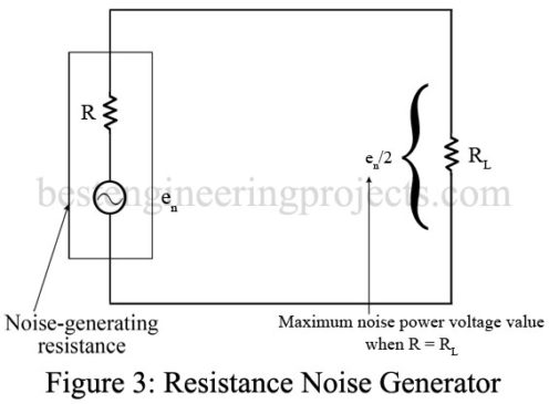
Electrical noise may be defined as any undesired voltages or currents that ultimately end up appearing in the receiver output. To the listener, this electrical noise often manifests itself as static. It may only be annoying, such as an occasional burst of static, or continuous and of such amplitude that the desired information is obliterated. Electrical noise signals at their point of origin are generally very small, for example, at the microvolt level. You may be wondering, therefore, why they create so much trouble. Well, a communications receiver is a…
Read MoreLithium Ion Battery Charger Circuit using LM317
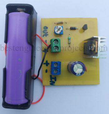
A Lithium-Ion Battery Charger Circuit using LM317 charges the battery in two different modes: constant current mode and constant voltage mode. Lithium polymer or lithium-ion batteries are very prone to overcharging or charging with high voltage or high current. Thus, when designing the charger circuit for Li-ion or Li-Po, we must consider a few things, such as charging voltage and current. The circuit posted here is designed using one of the famous variable voltage regulators, IC LM317. This circuit charges the battery in two modes, i.e., constant current and voltage.…
Read More15+ Waveguide Symbol
In this article, we will discuss the basics of waveguides and show 15 different types of waveguide symbols. Introduction of Waveguide Any surface separating two media of distinctly different conductivities or permittivities has a guiding effect on electromagnetic waves. For example, a rod of dielectric material, such as polystyrene, can carry a high-frequency wave, somewhat as a glass fiber conducts a beam of light. The best guiding surface, however, is between a good dielectric and a good conductor. In a broad sense, all kinds of transmission lines, including coaxial cables…
Read More