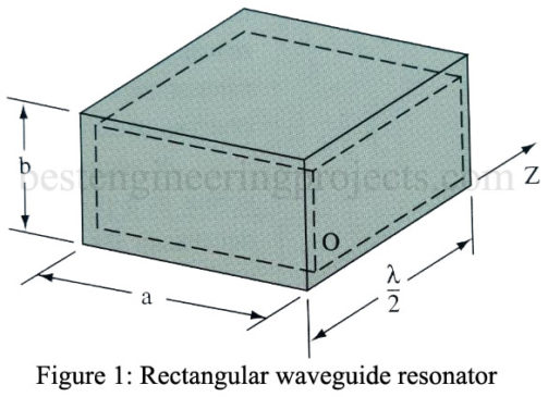
What is Cavity Resonator? Circuits composed of lumped inductance and capacitance elements may be made to resonate at any frequency from less than 1 Hz to many thousand megahertz. At extremely high frequencies, however, the physical size of the inductors and capacitors becomes extremely small. Also, losses in the circuit become extremely great. Resonant devices of different construction are therefore preferred at extremely high frequencies. In the UHF range, sections of parallel wire or coaxial transmission lines are commonly employed in place of lumped constant resonant circuits. In the microwave…
Read MoreCoupling Waveguide Energy
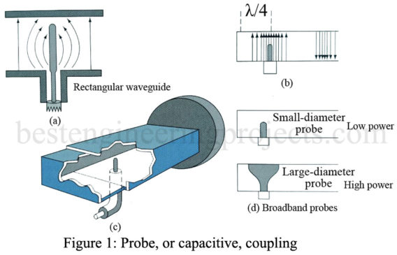
Fundamentally, there are three methods of coupling waveguide energy into or out of a waveguide: probe, loop, and aperture. Probe, or capacitive, coupling waveguide energy is illustrated in Figure 1. Its action is the same as that of a quarter-wave Marconi antenna. When the probe is excited by an RF signal, an electric field is set up [Figure 1(a)]. The probe should be located in the center of the dimension and a quarter wavelength, or odd multiple of a quarter Wavelength, from the short-circuited end, as illustrated in Figure 1(b).…
Read MoreWhat is Directional Coupler?
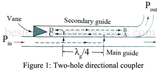
What is a Directional Coupler? The two-hole directional coupler consists of two pieces of waveguide with one side common to both guides and two holes in this common side. Its function is analogous to directional couplers used for transmission lines. The sections may be arranged physically either side by side or one over the other. The directional properties of such a device can be seen by looking at the wave paths labeled A, B, C, and D in Figure 1. Waves A and B follow equal-length paths and thus combine…
Read MoreWaveguide Termination and Attenuation
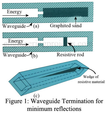
Waveguide Termination: Since a waveguide is a single conductor, it is not as easy to define its characteristic impedance (Z0) as it is for a coaxial line. Nevertheless, you can think of the characteristic impedance of a waveguide as being approximately equal to the ratio of the strength of the electric field to the strength of the magnetic field for energy traveling in one direction. This ratio is equivalent to the voltage-to-current ratio in coaxial lines on which there are no standing waves. For an air-filled rectangular waveguide operating in…
Read MoreWaveguide Tee | Types of Tees
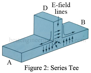
Waveguide Tees are microwave devices that are used to either divide the power of waveguides or combine the power of waveguides. Waveguide Tee is named after the English alphabet “T” and is of three types named according to their design. Types of Waveguide Tee Shunt tee or E-plane tee [Figure 1]: A shunt tee is so-named because of the sidearm shunting the E field for TE modes, which is analogous to voltage in a transmission line. It can be seen that if two input waves at arms A and B…
Read MoreWaveguide Attenuation | Bends and Twists
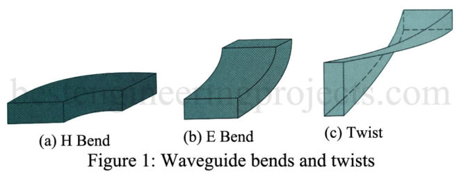
Waveguides are capable of propagating huge amounts of power. For example, typical X-band (0.9 x 0.4 in) waveguides can handle 1 million W if operated at 1.5 times fco, and an air dielectric strength of 3 x 10⁶ V/m is assumed. At frequencies below cutoff, the waveguide attenuation is very rapid. At frequencies above the cutoff, the guide supports traveling waves, and they are slightly attenuated because of losses in the conducting walls and in the dielectric that fills the guide. For air-filled guides, the dielectric loss is normally negligible,…
Read MoreTypes of Waveguides | Circular | Ridged | Flexible
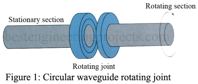
In the article “Types of Waveguides” we will discuss circular waveguides, rigid waveguides, and Flexible waveguides. Types of Waveguides Circular Types of Waveguides: The dominant mode (TE10) for rectangular waveguides is by far the most widely used. The use of other modes or other shapes is extremely limited. However, the use of a circular waveguide is found in radar applications where it is necessary to have a continuously rotating section such as in Figure 1. Modes in the circular waveguides can be rotationally symmetrical, which means that a radar antenna…
Read MorePhysical Picture of Waveguide Propagation
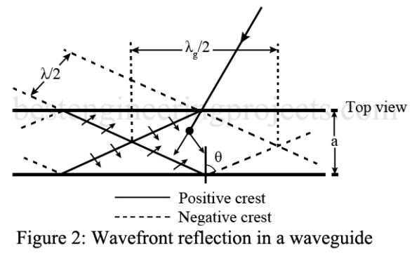
For a wave to exist in a waveguide, it must satisfy Maxwell’s equations throughout the waveguide. These mathematically complex equations are beyond the scope of this article, but one boundary condition of these equations can be put into plain language: There can be no tangential component of the electric field at the walls of the waveguide. This makes sense because the conductor would then short out the E field. An exact solution for the field existing within a waveguide is a relatively complicated mathematical expression. It is possible, however, to…
Read MoreWaveguide Operation | Dominant Mode
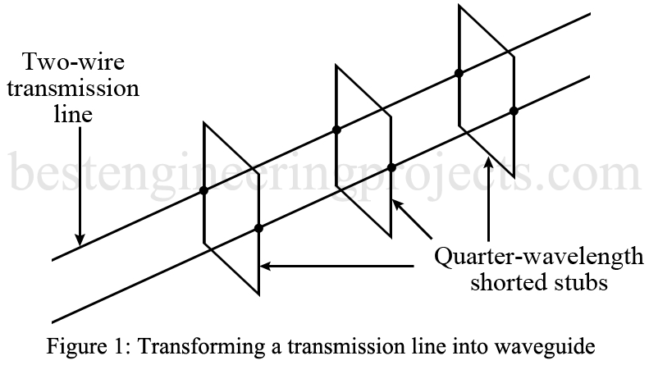
A rigorous mathematical demonstration of waveguide operation is beyond our intentions. A practical explanation of waveguide operation is possible by starting out with a normal two-wire transmission line. If an infinite number of these supports were added both above and below the two-wire transmission line as shown in Figure 1, you can visualize it turning into a rectangular waveguide. Waveguide Operation If the shorted stubs were less than a quarter wavelength, the operation would be drastically impaired. The same is true of a rectangular waveguide. The a dimension of a…
Read MoreAutomatic Submersible Pump Controller Circuit
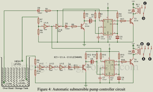
The automatic submersible pump controller circuit posted here is used to automate the operation of an electrical submersible pump (ESP) based on the level of water in the overhead tank. The Automatic submersible pump controller circuit can be used as a standalone system and can be interfaced with the existing manual control panel. Introduction to electrical submersible pump (ESP) Electrical submersible pumps, often called ESP are single or multiple-stage radial flow pressure series impeller pumps that are closely coupled to the motor for low and medium heads. ESPs are efficient…
Read More