How to Arduino Thermocouple Interface: In this article, you will learn about interfacing K-type thermocouples and display temperature in Celsius and Fahrenheit on I2C LCD.
Introduction of Thermocouple
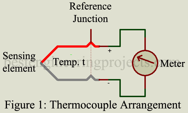
A thermocouple consists of a pair of dissimilar metal wires joined together at one end, called a sensing junction, and terminated at the other end, called the reference junction which is maintained at a known constant temperature called the reference temperature. When the sensing junction and the reference junction are at different temperatures, a potential difference gets produced which causes a current in the circuit, this effect is called the Seebeck effect. Microammeter or a recording instrument is connected across the reference end as shown in figure 1. Then the meter current is proportional to the temperature difference between the hot junction and the reference junction.
The magnitude of the thermal emf v depends on the wire material used and on the temperature difference (t-t0) between the junctions and may be expressed as below:
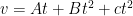
Where t is the sensing junction temperature and A, B, C is constants of the thermocouple material.
The simplest temperature measurement using a thermocouple is by connecting a sensitive millivoltmeter directly across the cold junction. The deflection of the meter is directly proportional to the difference in temperature between the sensing junction and the reference junction. However, this method suffers from the drawback that the thermocouple can supply very limited power to drive the meter movement and is, therefore, not commonly used. An amplifier with a proper circuit is most commonly used to indicate temperature.
Advantage of Thermocouple
- Cheaper in comparison to RTD (Resistance Temperature Detector). Check out the article on how to measure temperature using PT100 and Arduino)
- Wide temperature measuring range i.e. -2700C to 27000C
- Does not require a bridge circuit and hence good sensitivity in comparison to RTD.
- Response to temperature change is quite good in the range of 0.2 seconds.
- It has rugged construction and can be used in harsh environments like extremely hot or cold.
Disadvantage of Thermocouple
- Temperature sensitivity is poor in comparison to semiconductor-type sensors. checkout the article on How to get stable temperature using LM35 (LM35, DS18B20).
- Need proper amplifier and cold junction compensation because output voltage is very small in a range of few microvolts.
- Thermocouples might pickup stray voltage.
- It might show non-linearity.
Several types of circuits have been developed for automatic recording of temperature and the automatic control unit.
Check the article on
In the article, we are going to measure temperature using a K-type thermocouple and a MAX6675.
Working Principle of Thermocouples
The output produced from the Seebeck effect is called thermoelectric emf and in the range of uV. This voltage is so small that, no microcontroller can detect it. Thus, we need a voltage amplifier circuit with higher gain. As measure voltage at the colder end thus we also need cold function compensation. The output of thermocouples is analog and for that, we need an analog to digital converter (ADC).
The output of the thermocouple is converted in digital voltage in three steps
- Cold junction compensation
- High gain voltage amplifier
- analog to digital converter
For all the above operations we use an IC MAX6675 because it has inbuilt all the features we need.
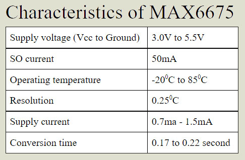
MAX6675 is a cold junction compensates k thermocouple amplifier IC from Maximum Integrated. It has features like
- Inbuild cold-junction compensation, ADC, and high gain voltage amplifier.
- Serial peripheral interface i.e. SPI compatible interface
- 12-bit with 0.250C resolution
- Automatic k-type thermocouple detection.
Components Required for Arduino Thermocouple Interface
- Arduino UNO / NANO x 1
- MAX6675 breakout board x 1
- Type K thermocouple with connector x 1
- 16×2 I2C LCD x 1
- Breadboard x 1
- USB Cable for Arduino programming
- Connector
Description of Arduino Thermocouple Interface
The circuit is designed around Arduino UNO, MAX6675, and 16×2 I2C LCD. (You can also use Arduino nano without any modification in circuit and code).
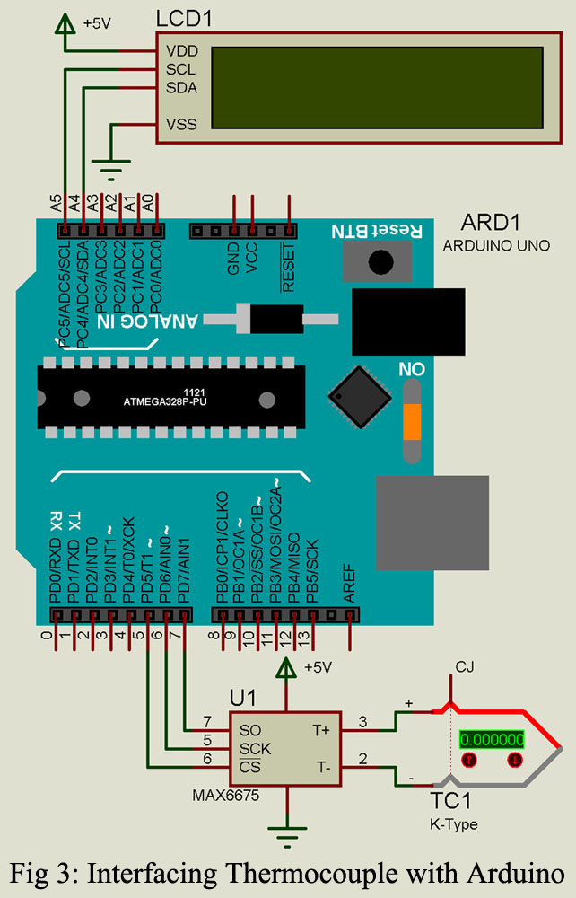
The thermocouple is connected to the header connected to the MAX6675 breakout board, where the RED terminal of the thermocouple is connected to the positive (+) terminal and the blue is connected to the negative (-) terminal. Polarity is very important here, so before connection make sure of polarity and connect it to the corresponding terminal. 5V and GND from Arduino are connected to VCC and GND pin of MAX6675 breakout board respectively. SPI pin of MAX6675 i.e. CS, SCK, and SO is connected to Arduino pin D5, D6, and D7 pin.
Here, we are using I2C 16×2 LCD to display the value of temperature and other parameters. SDA and SCL pin of LCD is connected to I2C pin of Arduino UNO i.e. SDA (A4) and SCL (A5) Pin respectively.
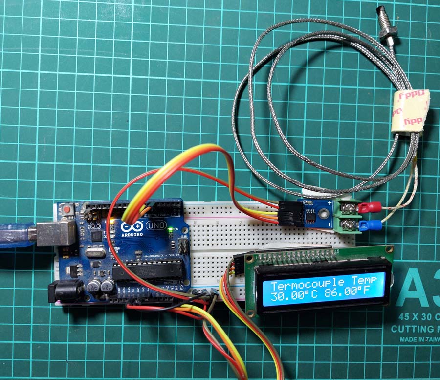
Figure: Author Prototype of Arduino Thermocouple Interface
Software Code: Software code is written in Arduino programming language and compiled using Arduino IDE.
|
1 2 3 4 5 6 7 8 9 10 11 12 13 14 15 16 17 18 19 20 21 22 23 24 25 26 27 28 29 30 31 32 33 34 35 36 37 38 39 40 41 42 43 44 45 46 47 48 49 50 51 52 53 54 55 56 57 58 59 60 61 62 63 64 65 66 |
#include <SPI.h> #include <LiquidCrystal_I2C.h> LiquidCrystal_I2C lcd(0x26,16,2);//address of lcd, column no, row no. #define CS 5 #define SO 7 #define SCK 6 void setup() { lcd.init(); // initialize the lcd lcd.backlight(); //Backlight ON } void loop() { float temp_C = Thermocouple_read(); if (isnan(temp_C)) { lcd.setCursor(0,0); lcd.print("Connect"); lcd.setCursor(0,1); lcd.print("Thermocouple"); delay(1000); loop(); } float Temp_fn = (temp_C*1.8)+32; lcd.setCursor(0,0); lcd.print("Termocouple Temp"); lcd.setCursor(0,1); lcd.print(temp_C,2); lcd.print((char)223); lcd.print("C"); lcd.setCursor(8,1); lcd.print(Temp_fn,2); lcd.print((char)223); lcd.print("F"); delay(1000); } double Thermocouple_read() { lcd.clear(); uint16_t v_out; pinMode(CS, OUTPUT); pinMode(SO, INPUT); pinMode(SCK, OUTPUT); digitalWrite(CS, LOW); delay(1); v_out = shiftIn(SO, SCK, MSBFIRST); v_out <<= 8; v_out |= shiftIn(SO, SCK, MSBFIRST); digitalWrite(CS, HIGH); if (v_out & 0x4) { //Thermocouple is disconnected return NAN; } // The lower three bits (0,1,2) are discarded status bits v_out >>= 3; // The remaining bits are the number of 0.25 degree (C) counts return v_out*0.25; } |
Software Description
Library and pin definition: Here, we are using two libraries one for SPI communication and the other for I2C LCD. No dedicated library for temperature measurement is used. The code is simple and easy, at first we define the address, number of columns, and number of rows of I2C LCD. After that, we define the pin for MAX6675.
|
1 2 3 4 5 6 7 8 |
#include <SPI.h> #include <LiquidCrystal_I2C.h> LiquidCrystal_I2C lcd(0x26,16,2);//address of lcd, column no, row no. #define CS 5 #define SO 7 #define SCK 6 |
setup function: In this function LCD is initialized and the backlight function is called in order to glow the backlight of the LCD.
|
1 2 3 4 5 |
void setup() { lcd.init(); // initialize the lcd lcd.backlight(); //Backlight ON } |
void function: In this function, we call the Thermocoule_read function which returns the measured temperature value. When the returned value is nan (not a number) then it displayed the message “connect thermocouple” and recall the loop function. But if the value is number type then it first converts the Celsius to Fahrenheit and displays the temperature value in Celsius as well as Fahrenheit.
|
1 2 3 4 5 6 7 8 9 10 11 12 13 14 15 16 17 18 19 20 21 22 23 24 |
void loop() { float temp_C = Thermocouple_read(); if (isnan(temp_C)) { lcd.setCursor(0,0); lcd.print("Connect"); lcd.setCursor(0,1); lcd.print("Thermocouple"); delay(1000); loop(); } float Temp_fn = (temp_C*1.8)+32; lcd.setCursor(0,0); lcd.print("Termocouple Temp"); lcd.setCursor(0,1); lcd.print(temp_C,2); lcd.print((char)223); lcd.print("C"); lcd.setCursor(8,1); lcd.print(Temp_fn,2); lcd.print((char)223); lcd.print("F"); delay(1000); } |
Thermocouple_read() function: This function is used to measure the temperature using thermocouples and return the value. When the thermocouple is not connected then it returns nan (not a number), but when the thermocouple is connected it returns the temperature value which is basically voltage multiplied by 0.25 (resolution of MAX6675).
|
1 2 3 4 5 6 7 8 9 10 11 12 13 14 15 16 17 18 19 20 21 22 23 24 25 26 27 |
double Thermocouple_read() { lcd.clear(); uint16_t v_out; pinMode(CS, OUTPUT); pinMode(SO, INPUT); pinMode(SCK, OUTPUT); digitalWrite(CS, LOW); delay(1); v_out = shiftIn(SO, SCK, MSBFIRST); v_out <<= 8; v_out |= shiftIn(SO, SCK, MSBFIRST); digitalWrite(CS, HIGH); if (v_out & 0x4) { //Thermocouple is disconnected return NAN; } // The lower three bits (0,1,2) are discarded status bits v_out >>= 3; // The remaining bits are the number of 0.25 degree (C) counts return v_out*0.25; } |
hello,
help for PT1000
how can connect with arduino?
BEst
danny
Hi, Danny
We had already posted a complete article and video on how to interface PT100 with Arduino. please go through the link.
https://bestengineeringprojects.com/measuring-temperature-using-pt100-and-arduino/