The availability of low-cost PLL and programmable divider ICs has led to the use of synthesizers in virtually all channelized transceivers. This is true even for the very low-cost systems used on the 40-channel citizen band transceiver.
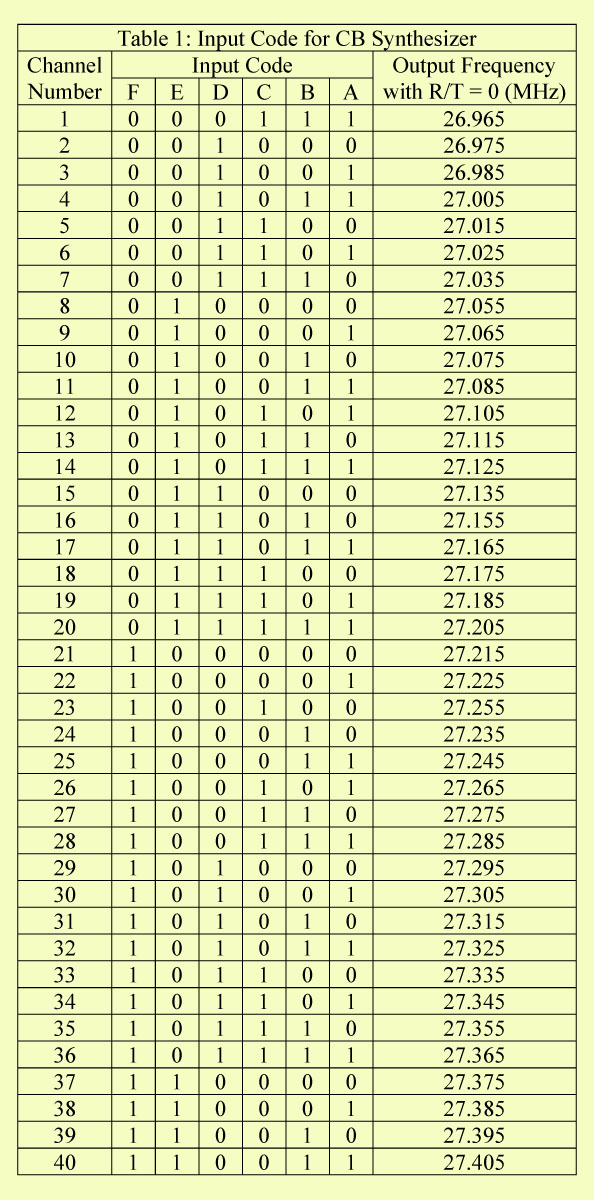
The circuit of the 40 Channel Citizen Band Transceiver is shown in Fig. 1 allows all necessary frequencies for a CB transceiver to be generated by using a single-crystal oscillator. The 40 channels are spaced at 10-kHz intervals (with some gaps) between 26.965 and 27.405 MHz. Local oscillator frequencies for the reception of these channels with intermediate frequencies of 455 kHz, 10.240 MHz, and 10.700 MHz are also synthesized. Table 1 shows the relationship between the program input and the channel selected. By using a program other than one of the 40 given, other frequencies may be selected-in fact, there are 64 channels at 10-kHz separation available from 26.895 to 27.525 MHz and programming starts at all zeros on input A through F for 26.895, and each increase of one bit to the binary number on these inputs increases the channel frequency by 10 kHz until all 1s give 27.535 MHz. The A input is the least significant bit, and F is the most significant.

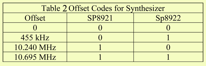
The programming input on pin 16 of the SP8922 IC in Fig. 8-18 is normally kept high, but making it low increases the programmed frequency by 5 kHz. Table 2 shows the programming required to obtain various offsets. This synthesizer is intended for use in double conversion receivers with IFs of 10.695 MHz and 455 kHz and generates either the frequency programmed or the frequency programmed less than 10.695 MHz.
If other offsets are programmed in connections to pin 15 of the SP8921 IC and pin 2 of the SP8922 IC, they must be altered according to Table 2. The synthesizer consists of the SP8921 and the SP8922 plus an SP1648 voltage-controlled oscillator. The programming inputs to the SP8922 are as shown in Table 1. Logic 1 is +3 V or more; logic 0 is either ground or an open circuit.
The crystal oscillator in the SP8921 (Fig. 1) is trimmed by a small variable capacitor, C3, which must be set up during the alignment of the synthesizer so that the output frequency on pin 4 is 10.240000 MHz. The only other adjustment is to set the core of L1 so that the varicap control voltage (D1) is 2.85 V when the synthesizer is set to channel 30 transmit. Since the difference between transmit and receive frequencies is over 10 MHz, it is not possible to tune both with the same tuned circuit, and an extra capacitor is switched using a diode during the reception.
The phase/frequency comparator of the SP8921 can have an output swing from 0.5 V to 3.8 V, but it is better to work in the range of 1.5 to 3.0 V, as the phase-error output voltage is more linear in this region. The ZC822 tuning diode specified for this synthesizer may be replaced by any other tuning diode provided that it will tune the VCO over the required range, or a little more, as the control voltage goes from 1.5 V to 3.0 V. With slight coil changes the MV2105 has been used successfully in this synthesizer.
The low-pass filter of the PLL consists of C5, C6, and R3. If a faster lock (at the expense of larger noise and reference sidebands) is required, the filter may be redesigned. If the synthesizer is used in a scanning receiver, a switched filter should be used to give a fast lock during scanning but a slower lock and cleaner signal during normal operation. A scanning receiver automatically “searches” several channels until it finds a good received signal. It then stays tuned to that channel until “nudged” by the operator and/or the reception is lost. The lock output on pin 8 of the SP8921 is used to light an indicator when the loop is not locked and should also be used, in a transmitter or transceiver, to prevent transmission when the loop is unlocked.
It requires a single +5-V supply and draws about 60 mA. The performance is improved if a double-sided board is used with a ground plane on one side. A small further improvement would come from the use of a grounded screening can over the whole system to prevent stray noise pickup.
The synthesizer has reference frequency sidebands 50 dB down at 1.25 kHz from the carrier. All output over 5 kHz from the carrier is over 70 dB down. Lock time for a change from channel 0 to channel 40 (a frequency change of 440 kHz) is around 35 ms. Stepping from transmitting to receive, or vice versa takes somewhat longer because of the much larger change of frequency but is generally complete within 75 ms.