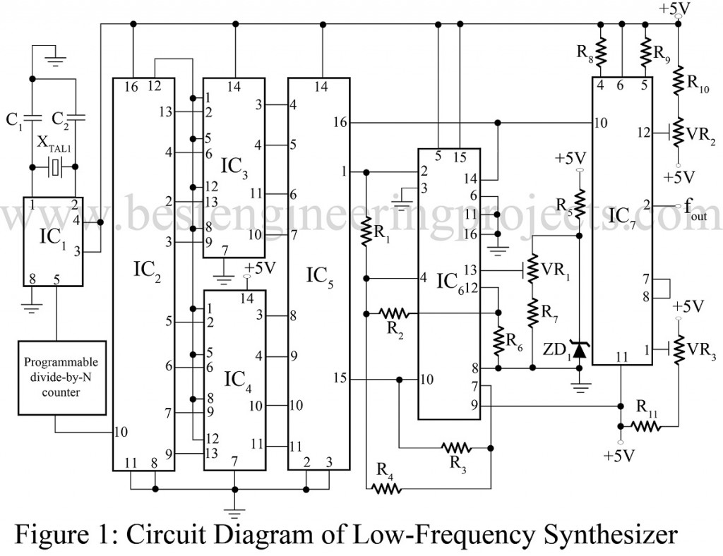
The generation of low frequency is generally accomplished with an RC oscillator. The techniques recently developed for frequency synthesis can now be used conveniently with very precise low frequencies required. A low-frequency sine-wave synthesizer well demonstrates accuracy and stability characteristics that can be measured in part per million (even at 0.01 Hz) if it is crystal controlled.
Circuit Description of Low Frequency Sine Wave Synthesizer
The synthesizer in figure 1 is based on an 8-bit digital-to-analog converter IC AD7523 (IC5) which presents a precise triangle wave to the timing of a function-generator chip IC ICL8038 (IC7). The converter receives an 8-bit code from an up/down counter IC CD4040B (IC2) which operates at a frequency 29 times greater than the desired sine-wave output. The crystal frequency required is
The phase of the output sine wave can be precisely controlled by using a presettable up/down counter to determine the cycle start point. For easy frequency-shift-keying (FSK), a programmable divide-by-N counter is placed after the crystal oscillator. By digitally controlling N, the user modulates the sine-wave output frequencies.
The amplitude of the converter’s triangle-wave output is adjusted by VR1 to approximately 3.3V p-p. Variable resistors VR2 and VR3 are adjusted to give the lowest distortion to the output sine wave. This low-frequency sine wave synthesizer consumes about 100mW and can be used in portable equipment.
The crystal control has two advantages over another method for generating low frequency sinusoidal. First, the circuit’s temperature stability is superior because the crystal determines these characteristics; the RC sine-wave oscillator depends on stable and accurate resistors and capacitors to get good temperature performance. Second, unlike the RC oscillator the required tuning, the synthesizer crystal-controlled approach required no trimming to get accurate frequencies.
PARTS LIST OF LOW FREQUENCY SINE WAVE SYNTHESIZER
| Resistor (all ¼-watt, ± 5% Carbon) |
| R1 = 20 KΩ
R2 – R4, R6, R10, R11 = 10 KΩ R5 = 24 KΩ R7 = 13 KΩ R8, R9 = 1 MΩ VR1 = 10 KΩ VR2, VR3 = 100 KΩ |
| Capacitors |
| C1, C2 = as per crystal required |
| Semiconductors |
| IC1 = ICM7209 (Clock Oscillator)
IC2 = CD4040B (12-bit counter) IC3, IC4 = CD4070B IC5 = AD7523 (8-bit DAC) IC6 = ICL7631 (Low power op-amp) IC7 = ICL8038 (Function generator) ZD1 = ICL8069 (Zener diode) |
| Miscellaneous |
| XTAL1 = As per fout required |
