Basically, RGB represent three basic colour RED GREEN and BLUE which is used in our digital system for generation various other colour. The project ‘RGB Colour Generator using Arduino’ is basically a tutorial on how to generate colour code and hex code of that color.
Circuit Description of RGB Colour Generator using Arduino
The circuit of RGB colour generating using arduino is basically designed using a microcontroller unit (Arduino uno), a 16×2 alpha numeric LCD, a RGB LED and few resistor and variable resistor. The circuit diagram is shown in figure 1.
The 100Ω resistor is connected across anode at RGB1 as shown in circuit diagram these three resistors is basically current limiting resistor which control the flow of electron and save the RGB LED from burning. Variable resistor VR1 to VR3 is used to control the intensity of RGB LED. The wiper of VR1 is connected to analog pin A0 of arduino uno. Similarly, wiper of VR2 and VR3 is connected to pin A1 and A2 respectively. These variable resistor is used to control the intensity of RGB LED.
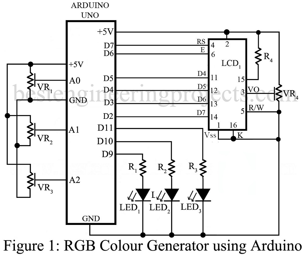
Resistor R4 is use to limit the current flowing to the backlight of LCD where variable resistor VR4 is used to adjust the contrast of LCD.
LCD is used here in order to display the value of color and hex value of colour code. The colour code value is displayed in 1st row of LCD where Hex code is displayed in 2nd row of LCD.
As the arduino board is of 8-bit thus it need to convert 10-bit digital value to 8-bit which is used to controlled the PWM duty cycle.
The colour value is showed in 1st row in the form of Rxxx Gxxx Bxxx where xxx represent the numerical value. The second row shows the HEX value in the form of HEXxxxxxx.
Other project using arduino posted in bestengineeringprojects.com
- Smart Dustbin using Arduino Uno
- Earthquake detector | Indicator Circuit using Vibration Sensor
- Car Lock System using Arduino and GSM
- Sound Level Meter Circuit using Arduino
- Arduino Based Car Reverse Alarm
Software Code:
The complete code of RGB Colour generating using arduino is written in arduino programming language and burned using Arduino IDE. The code is given below you can directly download and used in your projects.
|
1 2 3 4 5 6 7 8 9 10 11 12 13 14 15 16 17 18 19 20 21 22 23 24 25 26 27 28 29 30 31 32 33 34 35 36 37 38 39 40 41 42 43 44 45 46 47 48 49 50 51 52 53 54 55 56 57 58 59 60 61 62 63 64 65 66 67 68 69 70 71 72 73 74 75 76 77 78 79 80 81 82 83 84 85 86 87 88 89 90 91 92 93 94 95 96 97 98 99 100 101 102 103 104 105 106 107 108 109 110 111 112 113 114 115 116 117 118 119 120 121 122 123 |
#include <LiquidCrystal.h> // LCD library LiquidCrystal lcd(7, 6, 5, 4, 3, 2); //LCD diplay pins on Arduino int Radj; int Gadj; int Badj; int Rval=0; int Gval=0; int Bval=0; int R = 9; int G = 10; int B = 11; void setup() { pinMode(R, OUTPUT); // Pin 9 declared as output pinMode(G, OUTPUT); // Pin 10 declared as output pinMode(B, OUTPUT); // Pin 11 declared as output lcd.begin(16,2); // Initialise LCD delay(1); lcd.setCursor(0,0); lcd.print("RGB COLOUR"); lcd.setCursor(4,1); lcd.print("GENERATOR"); delay(2000); lcd.setCursor(0, 0); lcd.print(" R G B "); lcd.setCursor(3,1); lcd.print("HEX= "); } void loop() { Radj = analogRead(0); Gadj = analogRead(1); Badj = analogRead(2); Rval=Radj/4; // Convert the range from (0-1023) to (0-255) Gval=Gadj/4; // Convert the range from (0-1023) to (0-255) Bval=Badj/4; // Convert the range from (0-1023) to (0-255) lcd.setCursor(2,0); if (Rval<10) { lcd.setCursor(2,0); lcd.print("00"); lcd.print(Rval); } else if(Rval<100) { lcd.setCursor(2,0); lcd.print("0"); lcd.print(Rval); } else { lcd.setCursor(2,0); lcd.print(Rval); } lcd.setCursor(8,1); if (Rval<16) { lcd.print("0"); lcd.print(Rval, 16); } else { lcd.print(Rval, 16); } lcd.setCursor(7,0); if (Gval<10) { lcd.setCursor(7,0); lcd.print("00"); lcd.print(Gval); } else if(Gval<100) { lcd.setCursor(7,0); lcd.print("0"); lcd.print(Gval); } else { lcd.setCursor(7,0); lcd.print(Gval); } lcd.setCursor(10,1); if (Gval<16) { lcd.print("0"); lcd.print(Gval, 16); } else { lcd.print(Gval, 16); } lcd.setCursor(12,0); if (Bval<10) { lcd.setCursor(12,0); lcd.print("00"); lcd.print(Bval); } else if(Bval<100) { lcd.setCursor(12,0); lcd.print("0"); lcd.print(Bval); } else { lcd.setCursor(12,0); lcd.print(Bval); } lcd.setCursor(12,1); if (Bval<16) { lcd.print("0"); lcd.print(Bval, 16); } else { lcd.print(Bval, 16); } analogWrite(R, Rval); // PWM for Red colour analogWrite(G, Gval); // PWM for Green colour analogWrite(B, Bval); // PWM for Blue colour } |
PARTS LIST OF RGB COLOUR GENERATING USING ARDUINO
| Resistors (all ¼-watt, ± 5% Carbon) |
| R1, R4 = 100 Ω
R2 = 270 Ω R3 = 330 Ω VR1 – VR3 = 10 KΩ Potmeter VR4 = 10 k Ω Preset |
| Semiconductors |
| RBG1 = Common Cathode RGB LED
Board1 = Arduino Uno Board |
| Miscellaneous |
| LCD1 = 16×2 Alphanumeric Display |