The project “IC 555 based Automatic Evening Lamp” is simple and built around timer IC 555 and LDR. The bulb used in the circuit is turned on automatically in low light (evening) and turned off in the morning. Various other automatic night lamp circuit is already posted on betsengineeringprojects.com. Some are listed here, Automatic Night Lamp Circuit using TRIAC and SCR, Automatic night lamp using 7486 IC, Light Sensor Switch Circuit using LDR, and 741 IC. The circuit posted here is a standalone automatic evening lamp; simply you have to connect…
Read MoreDIY Distance Measurement using GPS and ATmega328P
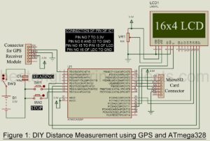
Whenever we thought about distance measurement, an image of a circuit designed using an ultrasonic sensor is formed in our minds. But today we are going to present here a distance measurement project using the GPS (Global Positioning Measurement) module. The project named DIY Distance Measurement uses GPS and ATmega328 which measure the distance between two positions using the haversine formula. The start point is the position where switch SW1 (Reading Switch) is pressed and the endpoint is the position when switch SW2 is pressed (Switch Switch). Thus, the circuit…
Read MoreDIY Soccer Substitution Board using AT89C51
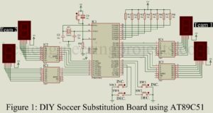
Various types of soccer substitution boards are easily available in the market but these all are very expensive (cost around $200). So, I decided to design a project called DIY Soccer Substitution Board using AT89C51. The feature of the project DIY soccer substitution board is listed below. Low cost and low maintenance. Microcontroller based system thus programmed as per our wish Simple and easily understandable circuit and code. Four individual buttons switch to increase and decrease the score of two teams. Circuit Description of DIY Soccer Substitution Board using AT89C51…
Read MoreDIY Breathalyzer using Arduino and MQ-3 Sensor Module
Few day ago, I got an email from one of reader of bestengineeringprojects.com asking about how does the traffic police know the concentration of alcohol present in our breadth. For that purpose, I had designed a project called DIY Breathalyzer using various easily available electronics components. Before starting about description of project I would like to describe what breathalyzer is. The breathalyzer or breathalyzer is an electronic device which is used to estimate the concentration of alcohol available in breath sample. This device is usually carried by traffic police, medical…
Read MoreAntenna Symbols | Symbols of Antenna
Before talking about various types of antenna symbols I would like to describe about antennas. Antennas for use at microwave frequencies. Antennas serve either or both of the following two functions: the generation and the collection of electromagnetic energy. In the transmission system, a radio-frequency signal is developed, amplified, modulated, and applied to the antenna. The RF current flowing through the antenna produces electromagnetic waves that radiate into the atmosphere. In a receiving system, electromagnetic waves “cutting” through the antenna induce alternating currents for use by the receiver. To have…
Read MoreMicrocontroller AT89C51 based Metro Train Prototype
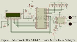
The project posted here is of Microcontroller AT89C51 based Metro Train Prototype which shows how metro train works. The project uses two motors, one is used for opening and closing the door and other is used for moving the train forward. This prototype of metro train is a good example of embedded system. Before talking about circuit description and working let clear the concept of embedded system. Embedded System: An embedded system is an electronic or electromechanical system designed to perform a specific function and is a combination of both hardware…
Read MoreDIY Digital Compass using ATmega8
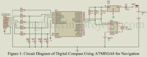
The DIY project Digital compass posted here utilizes an OLED display to show the direction (i.e. north). Another feature of this project is, it shows real data and time. DIY Digital Compass using ATmega8 A conventional compass utilizes a needle or a dial kept inside a compass rose. The conventional compass work on the principle of the earth’s magnetic field. But the projects DIY Digital Compass using ATmega8 posted here use the sun position to show the direction, unlike the magnetic field. Thus, this DIY Digital Compass is not affected…
Read MoreDIY Light Detector Circuit using LED
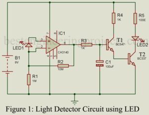
Today we come with a unique idea i.e. Photodiode using LED. This project utilized an LED to detect and respond to the presence and absence of light. Before starting the description and working of circuit DIY Light Detector Circuit using LED, we would like to describe a few electronics components. LED: Light-emitting diode is a photoelectric device that converts electrical energy into light energy. It is a heavily doped P-N junction diode that under forwarding bias emits spontaneous radiation. Photodiode: Photodiode is an optoelectronic device in which current carriers are…
Read More3000W Inverter with Inbuilt Charger using AT89C2051
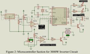
The project posted here is a 3000W inverter with the facility like an inbuilt charger, over and under voltage control, temperature control, microcontroller-based, etc. We all know that an inverter is a device that changes DC power into AC power (just opposite of a rectifier). The general-purpose inverter (low or medium power inverter) used in our house converts 12V DC voltage to 220V AC. But the circuit posted here converts 24V DC (two 12V batteries connected in series) to 220V AC. Circuit Description of Microcontroller Based 3000W Inverter with inbuilt…
Read MoreOpto Reflective Sensor using 555
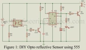
The DIY project posted here is of Opto Reflective Sensor using 555 IC and TCRT5000 module. These sensors are photoelectric sensors, which signifies that they rely on photo or light and do not need to be in contact with any other objects to sense. When a beam of light between the reflector and light sensor is interfered, that is when the sensor sends electrical signals. These electrical alerts are the information to the output unit. These days opto reflective sensor is used in various projects like proximity sensing, position detector,…
Read More
