When the battery is kept in the discharge state for a long period, irreversible chemical reaction takes place reducing the capacity of the battery so that eventually the battery becomes useless. No protection circuit can stop self discharge of the battery and only trickle charging on compensate for it.
Here is a circuit charging reminder for emergency light to inform the user that the battery has discharged itself below the safe level. The discharge characteristics of a dry battery, as supplied by its manufacturer indicate that the battery should not be discharge below a level of 1.7V per cell. The circuit charging reminder for emergency light is developed to given an audio alarm for about one second after a gap of about 30 seconds when the battery voltage fall below 5.1V. This kind of alarm is not annoying and yet can catch the attention of the user.
Circuit Description of Charging Reminder for Emergency Light
Transistor T5 and T6 along with R7 and C4 form an audio oscillator for driving a miniature speaker. This oscillator is enable for a period of about 1 second and disabled for 30 seconds by the output of the astable multivibrator formed by transistors T2 and T3 along with C2, C3, R3, R4 and R5. Transistor T1 along with R1, VR1 and ZD1 form level detector to sense the battery voltage.
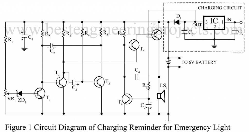
When the emergency light is plugged into the mains supply, the battery charger drives a current into the base of transistor T4 via R6. The saturated transistor T4 pulls down the base of transistor T5 and disables the audio oscillator.
While testing, this alarm circuit was found to work for a battery voltage as low as 1.3V. When the oscillator is enabled, the current drawn by the circuit is about 25mA at a battery voltage of 4V. As the oscillator is enabled only for 1 second is every 30 seconds, the loading effect of this circuit on the battery is negligible.
For testing and calibrating the alarm circuit, disconnect it from the charger and replace the battery by a variable DC supply. Adjust preset VR1 such that the audio oscillator is disabled for DC supply voltage of 5.1V and above. Reconnect battery and the charger the circuit is ready for use.
PARTS LIST OF CHARGING REMINDER FOR EMERGENCY LIGHT
|
Resistor (all ¼-watt, ± 5% Carbon) |
|
R1 = 560 Ω R2, R4, R7 = 220 KΩ R3, R5 = 10 KΩ R6 = 15 KΩ VR1 = 2.2 KΩ |
|
Capacitors |
|
C1, C2 = 100 µF, 25V (Electrolytic Capacitor) C3 = 4.7 µF, 25V (Electrolytic Capacitor) C4 = 0.1 µF (Ceramic Disc) C5 = 47 µF, 25V (Electrolytic Capacitor) C6, C7 = 0.01 µF (Ceramic Disc) |
|
Semiconductors |
|
IC1 = LM7808 (8V fixed series voltage regulator) T1 – T4 = BC147B (General purpose silicon NPN transistor) T5 = AC127 (General purpose germanium NPN transistor) T6 = AC128 (General purpose germanium PNP transistor) D1 = 1N4001 (Rectifier Diode) ZD1 = 3.3V (Zener Diode) |
|
Miscellaneous |
|
LS1 = 8Ω, loud speaker |