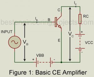
Transistor static characteristics curves are nonlinear. But for small signal operation, the point of operation moves about the quiescent operating point over a small range. Then the transistor parameters may be considered to be constant over this small range of operation. Derivation of h-Parameter model for transistor To drive the h-parameter model for a transistor, we consider the basic CE amplifier circuit of figure 1. The variable iB, iC, vB (=vBE) and vC(vCE) represent the instantaneous total values of currents and voltages. The input current iB and output voltage vC…
Read MoreUniversal Arduino IR Receiver Circuit
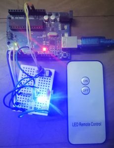
The project Universal Arduino IR Receiver Circuit works with any IR remote thus can control any electronic or electrical appliance like T.V., Fan, AC, Lighting bulb etc. Infrared Remote control as you know were introduce much earlier in the seventies. These day must electric/electronics device comes with inbuild infrared control system. Various devices like T.V., fan, AC or even a lighting bulb came with the features like remote control. But every IR receiver circuit responds only to assigned frequency i.e. it works only on fixed assigned frequency. Thus, every IR…
Read MoreLED Matrix Display using Arduino
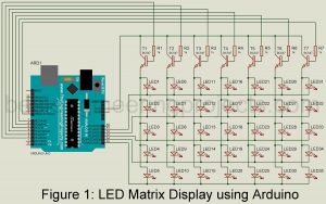
Today, I am going to teach you how to make an LED matrix display using Arduino. Here we had designed a 7×5 LED matrix display but can be extended as per desire. If you are using Arduino uno board the number of rows can be extended up to 14 and the number of columns can be extended up to 6. This is because there are only 14 digital pins (D0 to D13) and 6 analog pins (A0 to A5). Thus, you can make a 14×6 Led matrix display in the…
Read More5 Band Audio Equalizer Circuit using LM833
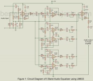
Today in this article we are going to show you the circuit diagram and description of the 5 Band Audio Equalizer Circuit using LM833. We already control 8W + 8W Stereo with a graphic equalizer, but this time we come with 5 Band Audio Equalizer Circuit. First, let’s talk about what an equalizer is. 5 Band Audio Equalizer Circuits using LM833 Equalizer circuits are those circuits that are responsible to maintain a balance between the frequency components. The project 5 Band Audio Equalizer Circuit using LM833 divides the audio spectrum…
Read MoreChristmas Music and Decoration using Arduino
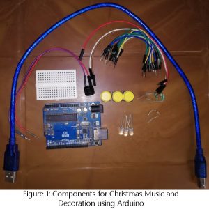
In this Christmas season I wanted to do some funny stuffs using arduino. Previously few years back I had made a project Christmas decoration and music using discrete components. Now I had come with funny easy and interesting project using arduino and few other easily available electronics components. The project posted here plays three different popular Christmas tone i.e. Jingle Bell Jingle Bell, wish you merry Christmas and Santa Claus is coming to town. The interest lies on the thing you have created with you owns. Definitely this project is…
Read MoreATmega16 Based Voting Machine
Atmega16 based voting machine: Well, the key word; Corruption is everywhere. I believe it is what comes together with politics. Yes, here we present an attempt to sweep a dirt away from this system. The project is concerned with development of an electronic voting machine which is built around an AVR microcontroller, which help us to create a fair election process at least. Electronic voting machines (EVMs) have been a necessity in government elections. On comparison to traditional methods, this machine provides a far more secure voting environment and reliable…
Read MoreCommon Emitter (CE) Amplifier | Operating Point
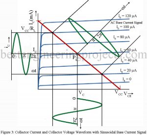
The Operating Point of Common Emitter Amplifier From the study of transistor characteristics, we find that amplification by transistor amplifier is most linear when the transistor operates in its active region. Hence the operating point must be suitably placed in the middle of the active region by suitable selection of external energy associated biasing circuit. Circuit Description of Common Emitter (CE) Amplifier Figure 1 gives the basic circuit of CE amplifier using NPN transistor bias through use of resistor Rb. Here capacitor Cb1, acts as the coupling capacitor to couple the…
Read MoreArduino based Bluetooth Controlled Car
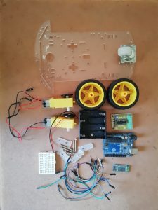
Today, we are going to show you how to make an Arduino-based Bluetooth Controlled Car. Previously we had already posted various types of robots like Arduino Gesture Controlled Robot, Dual Mode Robot, Arduino, and RF controlled Robot. The difference between previously posted robot projects and Arduino-based Bluetooth Controlled Car is, unlike others, that it does not require special types of control circuits. It can be controlled using any smartphone using the software. The best part of the project Arduino-based Bluetooth Controlled Car is you can wire it within an hour.…
Read MoreLED Cube 4x4x4 Circuit using AT89C2051
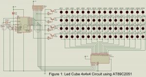
The world is all about visualization. Mesmerizing illumination has been introduced which provides a different level of satisfaction for human eyes. Using multi-pattern LEDs lights in a cubical representation is our contribution to this global trend. The project; LED Cube 4x4x4 Circuit using AT89c2051 microcontroller to create several light patterns. The cube designed for specific use in science laboratories is much easier to assemble. Previously, we had posted an LED Matrix Display using Arduino. Circuit Description of LED Cube 4x4x4 Circuit using AT89C2051 You can see the entire circuit of…
Read MoreAudio Oscillators
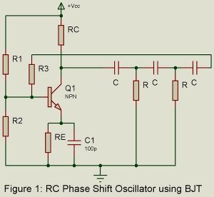
RC oscillators are principally used for generating audio frequencies. Two popularly used RC oscillators are (i) RC phase shift oscillator using either BJT or FET and (ii) Wien Bridge oscillator. Another popularly used audio oscillator is the Beat Frequency Oscillator (BFO). We here consider these three audio oscillators. RC Phase Shift Oscillator using BJT. Figure 1 gives the basic circuit. It is a sinewave feedback oscillator and uses an amplifier followed by three section R-C phase shift network. Output of the last section is fed to the base. We assume…
Read More