Amplifiers may be classified or Classification of Amplifiers in several ways as described below: According to the Frequency Range | Classification of Amplifiers Thus amplifiers may be classified as below: DC (Direct coupled) Amplifiers from zero frequency (dc) onwards. Audio Frequency Amplifiers 20 Hz to 20 KHz Video Frequency Amplifiers up-to a few MHz. Radio Frequency (RF) Amplifiers from a few KHz to hundreds of MHz. Ultra-high Frequency (UHF) and Microwave Amplifier up-to hundred or thousands of MHz. According to the method of operation | Classification of Amplifiers The position of the…
Read MoreApproximate h-model of CE, CB, CC amplifier
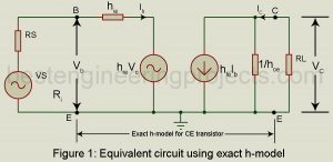
Approximate h-model: In the analysis of the transistor amplifier, we have as far used the exact h-model for the transistor. In practice, we may conveniently use an approximately h-model for the transistor which introduces an error of < 10% in most cases. This much error may be conveniently tolerated since the h-parameters themselves are not steady but vary considerably for the same type of transistor. We first derive this approximate CE h-model. Figure 1 gives the equivalent circuit of the CE amplifier using the exact h-model for the CE transistor.…
Read MoreAutomatic wiper for Automobile using Arduino and Rainsensor
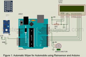
Automatic wiper for Automobile using Arduino and Rainsensor: The project we are talking about is an automatic screen wiper system that monitors the intensity of rainfall and controls the frequency of operation of the wiper accordingly. According to WHO, more than 1.25 million people die every year because of road crashes and mostly in rainy seasons. People end up dying because of small mistakes. Here we have forwarded an attempt to reduce that number. The project is especially suited for car. The project is centered around Arduino UNO board. So…
Read MoreComparison of CE, CB and CC Configurations
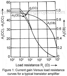
Comparison of CE, CB and CC Configurations: It is useful to study the variation of AI, AV and Ri with change in load resistance RL for each of the three configurations. Similarly, we may study variation of R0 with change of source resistance RS. Figure 1, 2 and 3 plots for each of the three configurations, current gain AI, voltage gain AV and input resistance Ri respectively as function of load resistance RL for the typically transistor whose h-parameters are given in Table 4.1. From these curves we get the…
Read MoreCommon Collector Amplifier or the Emitter Follower
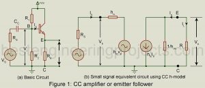
Common Collector Amplifier or the Emitter Follower: Figure 1(a) gives the basic circuit of a common collector amplifier, popularly called emitter follower. Its voltage gain is close to unity (one) and, therefore, any increment in the input voltage i.e. the base voltage appears as an equal increment in the output voltage across the load resistor in the emitter circuit. Thus, the emitter may be said to follow the input signal and hence the name emitter follower. The input resistance Ri of a CC amplifier or emitter follower is very high,…
Read MoreMetal Detector Circuit using Arduino
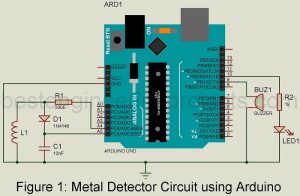
A metal detector circuit using Arduino is an electronics device that is used to detect metallic abject like metal coins, iron ore, aluminum or silver, gold, etc. This device can be used in a place where metal detection is mandatory like a hospital, airports, etc. because it can be harmful. We had already posted a simple metal detector circuit using transistors and RC components. The working principle is the same excepting the processing circuit. The metal detector circuit posted here uses an Arduino UNO board or equivalent. This project can…
Read MoreAnalysis of Common Base Amplifier (CB) using h-parameter
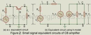
Analysis of Common Base Amplifier (CB) using h-parameter: Figure 1 gives the basic circuit of a transistor (NPN type) used as a common base (CB) amplifier. In this case, Vs is the signal voltage, Vi is the actual voltage at the input terminals and V0 is the output voltage. Figure 2(a) gives the a.c. equivalent circuit obtained on having removed the dc source. On replacing the CB transistor with its small-signal two generator h-parameter model we get the equivalent circuit of figure 1(b). Here also we assume sinusoidal input. Hence…
Read MoreAutomatic battery float charger circuit
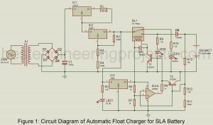
Automatic battery float charger circuit: This article aims to develop a battery charger circuit using the principle float charging technique. Afloat charger is also referred to as a smart charger, maintenance charger, or storage charger because it charges the battery at the same rate at which it self-discharges. The main reason for using a float charger is, that it protects the battery from overcharging and deep discharging. Thus, you can connect the float charger circuit to a battery for indefinite intervals of time i.e. there is no need to disconnect…
Read MoreAnalysis of Common Emitter Amplifier using h-parameters
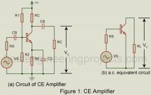
Analysis of Common Emitter Amplifier using H Parameter Figure 1(a) shows the circuit of a common emitter (CE) amplifier using self-bias and load resistor R0 capacitively coupled to the collector. Figure 1(b) gives the a.c. equivalent circuit. Here we have eliminated the biasing circuit consisting of R1, R2, Re, and Cz. The R1 – R2 combination is equivalent to resistance Rb (= R1 || R2) between base and ground. It is assumed that Rb is large in comparison with the input resistance of the amplifier between base and ground and…
Read MoreDIY Li-Fi Speaker | How to Design
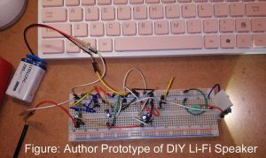
Here in the article I am going to show you “How to design DIY Li-Fi speaker” we are going to show you how to make Li-Fi speaker i.e. uses light to transfer data. This article consist of entire detail like design procedure, circuit diagram, and description. Introduction to Li-Fi (Light Fidelity) The term wireless has been gaining so much popularity in the recent years. Li-Fi is another block to growing platform. The term Li-Fi; Light Fidelity sounds somehow similar to Wi-Fi and they share a lot of common features. Both…
Read More
