A metal detector circuit using Arduino is an electronics device that is used to detect metallic abject like metal coins, iron ore, aluminum or silver, gold, etc. This device can be used in a place where metal detection is mandatory like a hospital, airports, etc. because it can be harmful.
We had already posted a simple metal detector circuit using transistors and RC components. The working principle is the same excepting the processing circuit. The metal detector circuit posted here uses an Arduino UNO board or equivalent. This project can be used to detect buried cables or any metallic object. This device starts to beep whenever it detects any metallic object.
Practical inductors (coils) uses at RF frequencies and above have an inductance rating in henrys and a maximum current rating. Inductors store energy in the surrounding magnetic field and loss (dissipate) energy in their winding resistance.
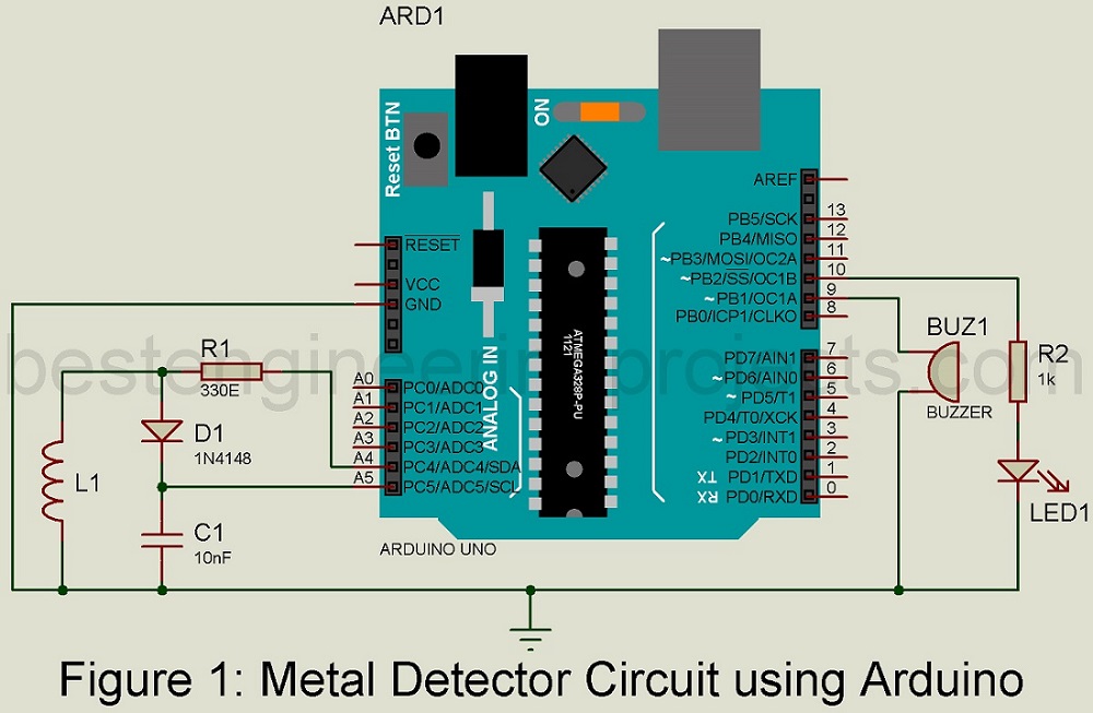
Circuit Description of metal detector using Arduino:
This metal detector circuit is shown in figure 1. This metal detector circuit is designed using an Arduino UNO board or equivalent, search coil, buzzer, 1N4148 diode, and a few other electronic components like resistor-capacitor, etc.
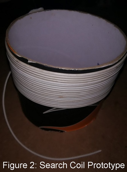
Construction of search coil for Metal Detector Circuit
A search coil comparison of 26 turns of wire, center-tapped. 24 SWG to 36 SWG gauges of wire can be used. Here we had constructed the search coil by winding the wire over a 10 cm diameter watch box as shown in figure 2.
Instead of a ferrite core coil, we used an air-core coil because when the search coil detects any metal, that metal piece acts as the core of the search coil. Thus, the overall inductor increases. The inductance of the inductor is depending upon the inner core of the coil.
Formula for calculating inductance of inductor is:
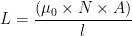
Where,  = absolute permeability and its value is
  for free space or air.
N = Number of turns
A = Inner core area in m2
l = length of wire in meter
Working on Metal Detector Circuit using Arduino
Here we used a parallel LC circuit. The parallel LC circuit is sometimes called a tank circuit. Energy is stored in each reactive element (L and C), first in one and then released to the other. The transfer of energy between the two elements will occur at a natural rate equal to the resonant frequency and is sinusoidal in form. The diode D1 is used as a resistor because it reduces the voltage. Resistor R1 is used as a current limiting resistor and thus limits the current to the Arduino pin.
For the audiovisual effect, we used a buzzer and a LED. When metal is detected, both buzzer and LED are activated.
LR tank circuit is connected to analog pin A4 and A5 which supply pulse and thus emf is generated. This generated emf is stored in a capacitor. The voltage across the capacitor is available at the Arduino analog pin. Arduino reads this voltage by using ADC, processes it, and produces output.
Software: The software code of the Metal detector circuit using Arduino is written in Arduino programming language and compiled using Arduino IDE. You can directly download the software code and use it in your metal detector project.
CLICK HERE TO DOWNLOAD THE SOFTWARE CODE
Components used in Metal Detector Circuit using Arduino
R1 = 330 Ω, resistor
R2 = 1 KΩ, resistor
C1 = 10nF, ceramic capacitor
D1 = 1N4148, diode
BUZ1 = Buzzer
LED1 = 5mm any color LED
Arduino UNO Board or equivalent