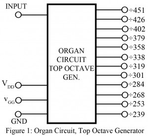
If you have observed quite a number of electronic projects, you must have noticed that different range of frequencies is used, sometimes all in a single project. To assist this requirement, this circuit “Organ Circuit” has been developed. The project entitled ‘Organ Circuit | Top-Octave Generator’ produces 12 distinct output frequencies. A single circuit produces 12 frequencies and each of them is different? Might sound a lot more complicated. However, the circuit uses only one parameter to serve this variation, which is the supplied input frequency to the chip. The…
Read MoreDark Sensor using Arduino
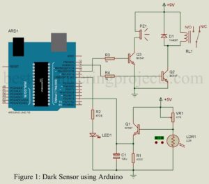
The project ‘Dark Sensor using Arduino’ uses an arduino board, a LDR and switching circuit. The circuit is basically a light operated circuit which operates when dark is detected on LDR. Circuit Diagram of Dark Sensor using Arduino. Circuit diagram of the projects ‘Dark Sensor using Arduino’ is shown in figure 1, build around a arduino uno board, a LDR, three transistors and few other electronics components. The LDR is basically a transducer which change one form of energy to another form (change in light intensity to change in resistance).…
Read MoreFM – IF System
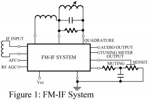
This IC includes a 3-stage FM-IF amplifier/limiter arrangement with level detectors for each stage and a balanced quadrature FM detector. As illustrated in Figure 1, the quadrature-tuned circuit requires two external coils, a capacitor and resistor and a single adjustment. Most ICs of this type also include an audio amplifier as well as a driving circuit for the tuning meter output, automatic frequency control (AFC) for the FM tuner, and AGC for the RF amplifier stage. The muting sensitivity control is optional and provides automatic muting (squelching), if desired. An…
Read MoreAM/FM RECEIVING SYSTEM
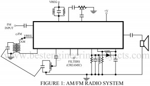
The circuit designed hereby constitutes of the major portion of every AM/FM receiving system. It can be used to design a complete AM/FM receiving system. Addition of components like audio power amplifier, AM converter (mixer and local oscillator, AMIE detector, FM IF and FM detector) form the internal building block of entire receiving system. However, for the receiving system to function flawlessly, external components like capacitors, coils, and resistors need to be included in the circuit which is obvious necessity. The operating characteristics such as bandwidth and gain of the…
Read MoreRGB Colour Generator using Arduino
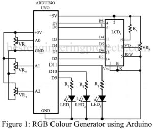
Basically, RGB represent three basic colour RED GREEN and BLUE which is used in our digital system for generation various other colour. The project ‘RGB Colour Generator using Arduino’ is basically a tutorial on how to generate colour code and hex code of that color. Circuit Description of RGB Colour Generator using Arduino The circuit of RGB colour generating using arduino is basically designed using a microcontroller unit (Arduino uno), a 16×2 alpha numeric LCD, a RGB LED and few resistor and variable resistor. The circuit diagram is shown in…
Read MoreSoil Moisture Meter using Arduino
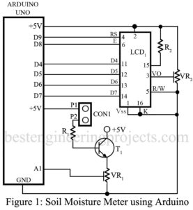
The project ‘Soil Moisture Meter using Arduino’ uses arduino board, a 16×2 LCD module and soil moisture sensor in order to display the humidity (moisture) of soil. This project is very useful for farmer, floriculture, researchers etc. in order to know the moisture of soil at different stage. The working principle and circuit description is very simple that anymore can understand who have little knowledge of arduino board. The project is basically an interfacing circuit between arduino board with LCD and sensor. Previously, we had posted Greenhouse Automation System for easy, cost effective,…
Read MoreArduino VU Meter
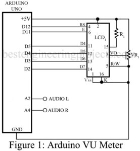
The project ‘Arduino VU Meter’ uses 16×2 alphanumeric LCD to display signal level of audio. Basically, VU Meter is used to represent volume of audio equipment. Previously we had posted a project Sound VU Meter using Arduino which uses LEDs to represent the level of volume where audio is taken from microphone. Unlike sound VU meter using arduino the project Arduino VU meter take input audio from two different channels i.e. left channel and right channel. Circuit Description of Arduino VU Meter The circuit of Arduino VU Meter is shown…
Read MoreTemperature Controlled Fan using Arduino
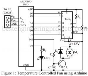
The project ‘Temperature Controlled Fan using Arduino is simply fabricated around Arduino uno board and temperature sensor LM35. The projects are a good example of embedded systems designed using a closed-looped feedback control system. For proper user interface visual indication we had also used LCD which indicate the temperature as well as the speed of the fan. Circuit Description of Temperature Controlled Fan using Arduino The entire circuit of ‘Temperature Controlled Fan using Arduino’ utilizes very few components, an MCU (Arduino Uno), a temperature sensor (LM35), an LCD, a motor…
Read MoreIndustrial Timer Circuit
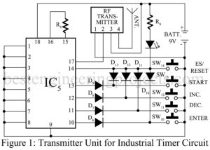
Humans are born of habits, they want more and more comfort. To match their requirements, various types of automatic control systems have been developed. Now, again here we have come up with a very interesting project called “Industrial Timer Circuit” with facilities like automation and switching, providing delay and having a long-range of control (100 m). A simple timer circuit can be designed using 555 timer IC by configuring it into monostable mode. These types of circuits have various types of limitations like digital display, an indication of system failure, remote…
Read MoreArduino FM Receiver Circuit using TEA5767
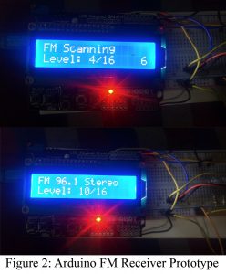
The circuit posted here is of Arduino FM Receiver using digital radio—receiver module TEA5657 by Philips. Additional components like audio power amplifier, Arduino uno board, and LCD module to display station number and frequency. However, for the receiving system to function flawlessly, external components like a capacitor, resistor, etc are included in the circuit, which is necessary. if you wish to make your FM transmitter circuit using Arduino please go through this link: Arduino FM Transmitter Description Arduino FM Receiver Circuit using TEA5767 The circuit of the project Arduino FM…
Read More