A multi-function calculator is designed within a single IC such that it executes five operations which include four basic arithmetic functions and one add-on or discount percentages. It constitutes of a simple layout of a keyboard with ten numerical keys, and six function keys plus a decimal point key. This IC is a general outline of simple calculator which can perform all of the logic and storage functions in one single, 28-pin IC. Light weight and inexpensive features add to flexibility in use of this calculator. Using the basic principle…
Read MoreComplex sound generator
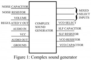
What is Complex sound generator? Internal noises; noise within a system, are treated as disturbances and we make attempts to reduce it to a lowest level possible. There is another way to eradicate noise and on the other hand, take benefits from the noise itself. It sounds completely insane, don’t you think so? The circuit we are going to discuss here reveals the mystery. The circuit entitled, ‘Complex sound generators’ makes use of this waste like internal noise and tones to produce special effect sounds. The disturbance is thus replaced…
Read MoreArduino FM Transmitter
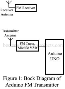
The project “Arduino FM Transmitter” is a radio station with transmits either voice or music nearby area, within the range of 50 meters range. The transmitted FM signal is received by any FM receiver. Previously, we had posted an Arduino-based FM Receiver with the facility of automating or manual tuning. The project uses very few components i.e Arduino uno board (MCU) and an FM transmitter V2.0 module. This project has various applications like it can be implemented in college hospitals etc. where announcements have to do. The block diagram of…
Read MoreDot/Bar Display Driver Circuit
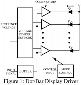
This project is all about LEDs. It gives basic guideline of how LEDs can be used to design something new in a better way. This article entitled; ‘DOT/BAR DISPLAY DRIVER CIRCUIT’ accepts variable input voltage and turns on one or more LEDs corresponding to the instantaneous voltage of the input. We can thus conclude that LEDs are here used to provide visual display of the magnitude of the input signal. Depending on the requirement, the circuit offers two modes of operation, out of which one produces a single moving dot…
Read MoreAutomatic Night Lamp Circuit
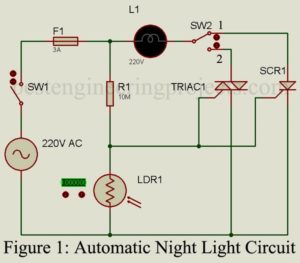
The project “Automatic Night Lamp Circuit” is very simple and built around four major components i.e. TRIAC, SCR, LDR, and Resistor. The lamp used in this project is a porch light that would turn on automatically in dark (nighttime) and turn off in light (daytime). Circuit Description of Automatic Night Lamp Circuit The circuit of Automatic Night Lamp Circuit is used shown in figure 1. The circuit is very simple and straightforward that anyone has very little knowledge about TRIAC and SCR. Silicon Controlled Rectifier | Automatic Night Lamp SCR…
Read MoreFluid Level Detector
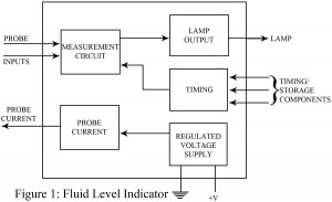
At times, determining the fluid level can become very tiresome. When the stored containers are dark-coloured, it gets more difficult. With automations taking over hectic activities, a special project, fluid level detector has been developed to eradicate this issue. The circuit of fluid level detector comes with a limitation; it can be used to measure non-flammable fluids only. In this particular circuit, the fluid level detector is used in conjunction with a thermo-resistive probe to measure the levels of fluids under consideration. A light is interfaced to one of the…
Read MoreVideo Game Circuit
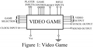
In comparison to multiple microprocessor controlled TV games, the game dedicated ICs differ quite a lot. The video game IC discussed here is a fine example of game IC which provides a selection of tennis, soccer, squash, practice, and two rifle shooting games. It can be a surprising fact that this multi-feature IC is the simplest form of game dedicated IC, available on the market. To add more, second IC can be included in the circuit to provide a colorful impact on the game. The video game circuit offers two…
Read MoreLED Flasher Circuit
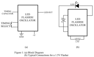
LEDs are probably the only components to offer a wide range of applications. It can be used either to describe the working of the circuit or with LED itself, a complete circuit can be developed. The LED flasher circuit makes use of this amazing component to turn it flash on and off. The LED flasher circuit employs a voltage source, capacitor, and LED. This project requires voltage supplies varying from 1.15 volts to 6 volts typically because of which the circuit can be operated with a single battery cell making…
Read MoreAuto Cut Circuit for Over and Under Voltage
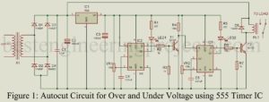
The project “Auto Cut Circuit for Over and Under Voltage” is designed to protect electrical and electronic devices from over and under voltage which ensures a long lifespan of this device. An “Auto Cut Circuit for Over and Under Voltage” has been presented here serving multiple purposes for security; under-voltage protection, over-voltage protection, auto reset, auto cut off, and regulation. Circuit Description of Auto Cut Circuit for Over and Under Voltage The circuit diagram of “Auto Cut Circuit for Over and Under Voltage” is shown in figure 1. The entire…
Read MoreVideo Game RF Modulator
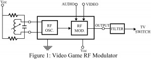
The project entitled, ‘ Video Game RF modulator’ is a small portion of the gaming circuit. Here this circuit can be divided into two different sections: an RF oscillator and the RF modulator, as per the functions each of them carry out. The oscillator section comprises an external LC network that is tuned to the preferred TV channel which is not used in the TV network, generally Channel 3 or 4. The audio and the composite video signal act as a modulator for the output signal (which act as the…
Read More