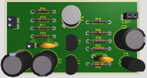
The Driver Amplifier amplifies the weak electrical signal from the microphone and makes it suitable for power amplification. Thus, an amplifier that is used before a power amplifier is called a driver amplifier. As all amplifier driver amplifier is also a cascade amplifier. Thus, by cascading multiple amplifier stages a project 10-Watt Audio Amplifier is built. Circuit Description of 10-Watt Audio Amplifier The project shown in figure 1 is of 10-Watt Audio Amplifier, which is basically a combination of various amplifiers i.e. pre-amplifier, driver amplifier, and a push-pull amplifier. Here…
Read MoreALARM CIRCUIT
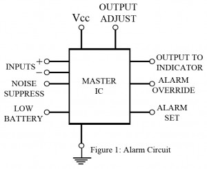
Alarm has today been established as a medium to alert people about the unusual happenings around the territory it is fixed at. This is a common circuit which makes uses of low power components and easily available electronic machinery to serve our purpose. To add more, because of the simplicity of this project, it can be implemented at places we sense the necessity. This IC benefits an individual with the possible list of options to select how s/he wants the alarm circuit to function, which includes necessary set-up for burglar…
Read MoreMultivibrator | Introduction | Types | Working
Introduction of Multivibrator We have already studied the working of several sinusoidal oscillators. For certain purposes, we need non-sinusoidal generators, also called relaxation oscillators. A relaxation oscillator generates voltage or current which varies abruptly one or more times in a cycle of operation. Typical examples of non-sinusoidal generators are: multivibrator, Schmitt trigger, UJT oscillators, blocking oscillators, saw-tooth (sweep) voltage generators, saw tooth (sweep) current generators etc. Multivibrators are used for various purposes such as generation of square waveforms, frequency counting, frequency division, generation of time delays and storage of binary…
Read More12V DC Ballast Circuit
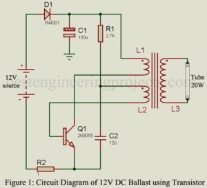
The project “12V DC Ballast” using power transistor 2N3055 is used to glow AC tube light using a DC source. The circuit of DC ballast is a DC-to-AC converter. DC ballast of various capacities (in watts) is already available in markets. The circuit posted here is of 20W capacity i.e. (it can drive a load up to 20 watts). Previously, we had posted Electronic Blast for Tube-light which drives load up to 40W, double the power of 12V DC Blast. Circuit Description of 12V DC Ballast The circuit of 12V DC…
Read MoreAppliance Timer
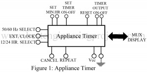
Generally, appliance timers offer a wide range of applications with a greater range of flexibility. But here we have presented a typical type of IC as shown in the figure, which can be used with 50/60 Hz power lines and can operate on both 12- or 24-hour basis. A 50 Hz power line requires an external clock input for operation. This clock turns the timer on/off and along with this also sets the minutes and hours limits of the timer. Additional features like ‘reset’ and ‘repeat’ control are added, which…
Read MoreDolby Noise Reduction Processor IC
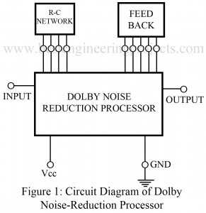
The IC described here is particularly designed for single audio channels, so as to offer Dolby B-type noise-reduction features. Along with the internal power supply regulator, the circuit of dolby noise reduction processor IC requires a series of amplifiers. In addition to this, some external RC networks are also required for the system. These networks serve a special purpose in the system. A single network comprising five capacitors and three resistors is connected to four external leads. The other network which constitutes of three resistors and three capacitors forms a…
Read MoreDigital AC/DC Voltage cum Continuity Tester
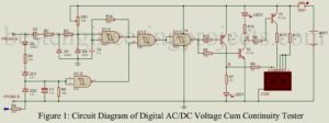
The project “Digital AC/DC Voltage cum Continuity tester” can be used to test 25 Volts to 500 volts AC/DC voltage continuity and open-circuit condition by displaying on the 7-segment display. There is the various advantage of “Digital AC/DC Voltage cum Continuity tester” over multimeter are Small Size, low cost, easy operation and requires no troublesome selector switch to select testing mode. To make a selector switch free circuit, we had used 82K impedance for DC and 220K impedance for AC. The testing procedure is very simple all you have to…
Read MoreAudio Power Amplifier
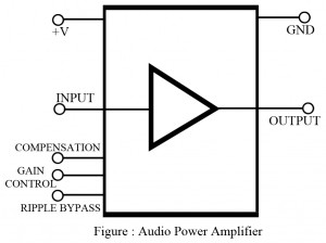
Generally, audio power amplifier are low frequency (typically 40 Hz to 20,000 Hz) power amplifiers. Internally, they are designed as class B power amplifiers and offer reasonable power gain (5 to 10 watts typically, as well as low distortion figures. To handle the power dissipation required, most chips have several large, flat pins that are tied to ground and act as heat sinks. Chips such as these provide additional features as well, such as thermal shutdown protection, overvoltage protection, and frequency compensation. The output is designed to drive a low…
Read MoreClock Circuit
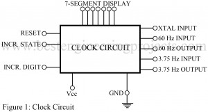
Clock Circuit Description:- Clocks are important companion of our daily life. They say, “Time and tide waits for none”. So, clocks play a vital role in our progressive routine. Wrist watches, table clocks are not the only devices available to display time, there are multiple ways to do so. The project discussed here draws the layout to build an electronic clock which provides all features like a normal clock does. Fascinating fact about this circuit is that it can be operated either from the AC power line, or from an…
Read MorePhase Sequence Change Indicator
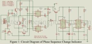
The project phase sequence change indicator using 555 IC is used to indicate whether there is a change in phase sequence occurring or not by a beeper or a LED. We all know that in three-phase motor phase sequence is important because the change in phase sequence may cause trouble in machines. Circuit Description of Phase Sequence Change Indicator The circuit of phase sequence change indicator is divided into two main sections i.e. controlling section and the beeper section. The circuit of the phase sequence change indicator is shown in…
Read More