The project “Digital AC/DC Voltage cum Continuity tester” can be used to test 25 Volts to 500 volts AC/DC voltage continuity and open-circuit condition by displaying on the 7-segment display. There is the various advantage of “Digital AC/DC Voltage cum Continuity tester” over multimeter are Small Size, low cost, easy operation and requires no troublesome selector switch to select testing mode. To make a selector switch free circuit, we had used 82K impedance for DC and 220K impedance for AC.
The testing procedure is very simple all you have to do is to touch its two probes at the required terminals of a circuit. The “U”, “C”, and “O” will appear on the display corresponding to voltage, continuity, or an open circuit condition respectively.
Despite all, this circuit has one another advantage i.e. for testing AC mains voltage it can be used as a mains tester with a single probe attached with the enclosure.
Circuit Description of Digital AC/DC Voltage cum Continuity Tester
The circuit of “Digital AC/DC Voltage cum Continuity Tester” is shown in figure 1, uses a CMOS quad dual-input Schmitt trigger NAND gate IC CD4093 with a few discrete components to work flawlessly. In normal condition (i.e. with probe A and B open circuit), pin 1 of gate N1 (IC1) is high, which enable N1 to produce a square wave. The frequency of the square wave is determined by R14 and C2 and kept in the range of 20 to 100 Hz. Since the total Zener voltage of ZD1 and ZD2 exceeds battery voltage (9V), Zener diode ZD1 bocks positive battery voltage ad the inputs of N2 remain pulled down by resistor R5.
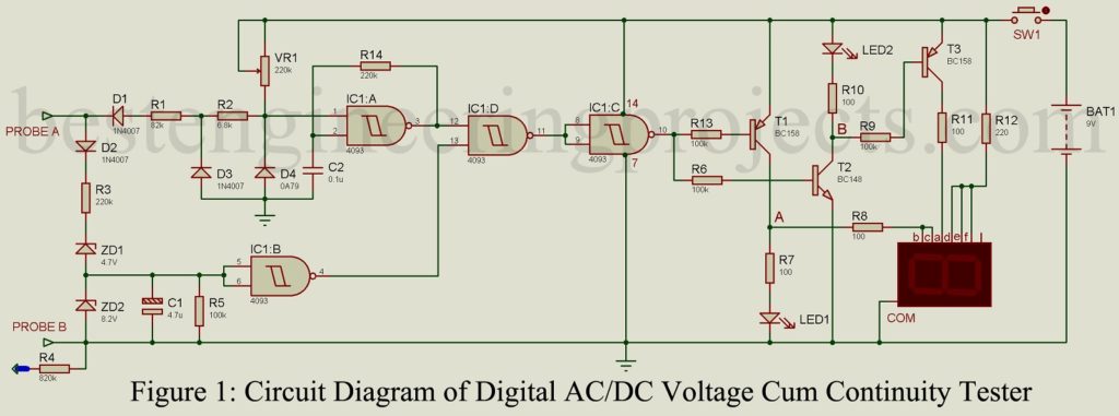
The corresponding high output of N2 enables gate N3 which passes the square wave produced by N1. The output of N4 becomes a square wave and further drives the buffer transistor T1, T2, T3, etc. The red and green LEDs glow alternately at a certain frequency. Due to the persistence of vision, both the LEDs seem to be glowing simultaneously.
Similarly, the output at points A and B consequently cause the display segments b, c, and a to glow alternately while segments d, e, and f glow continuously. This simulates the visual effect of “O” on the display.
Continuity Testing | Digital AC/DC Voltage cum Continuity Tester
In case of continuity, when probes A and B are short-circuited, the voltage at pin 1 of N1 goes a little below the lower threshold of the Schmitt trigger due to voltage divider action of R1, R2, and VR1. This disables gate N1, and since the input of N1, and since the input of N1 is also low, both the inputs of N3 become high. It causes the output of N4 to go to the continuously high state. Transistor T2 goes into saturation while T1 is cut-off. Therefore, the green LED (or display segment “a”) glows while red (or segments ‘b’ and ‘c’) goes off. The display now shows ‘C’.
Calibration | Digital AC/DC Voltage cum Continuity Tester
Variable resistor VR1 is a miniature preset, which is to be calibrated before use. Its calibration is fairly simple. Keep probes A and B short-circuited and the preset VR1 at its minimum value. Then increase the resistance value slowly till the RED LED goes off and only GREEN LED glows. For better results, increase the resistance slightly beyond that critical transition point.
AC/DC Voltage Testing | Digital AC/DC Voltage cum Continuity Tester
While testing for DC voltage (with probes A and B connected to the voltage source, probe A to positive and probe B to common), Zener diode ZD1 conducts and voltage at the inputs of N2 becomes equal to the Zener voltage of ZD2 (i.e. 8.2V). The corresponding low output state of N2 causes a low state at the output of N4. Now the RED LED (or segment b and c) glows, while GREEN LED (segment a) goes off indicating a voltage across the probes by displaying ‘U’.
For AC voltages, the positive half-wave only is used for the function of a tester, after being rectified by diode D2 smoothed and filtered by C1. The negative half-wave is dissipated by resistors R1 and R2 while diodes D3 and D4 are used to clip the negative voltage at pin 1 of N1. The negative voltage at pin 1 of N1 is equal to the forward voltage drop. Diode D3 is further used to minimize the negative forward current through D4 by sharing the maximum of the current through itself.
Check out other electronic tester circuits posted in bestengineeringprojects.com
- RJ45 Cable Tester Circuit
- Zener Diode Tester Circuit
- Servo Motor Tester Circuit Using 555 IC
- 5 State Digital IC and Circuit Tester
- 555 Timer IC Tester
PARTS LIST OF DIGITAL AC/DC VOLTAGE CUM CONTINUITY TESTER
| Resistors (all ¼-watt, ± 5% Carbon) |
| R1 = 82 KΩ
R2 = 6.8 KΩ R3 = 220 KΩ, 1 W R4 = 820 KΩ R5, R6, R9, R13 = 100 KΩ R7, R8, R10, R11 = 100 Ω R12 = 220 Ω VR1 = 220 KΩ, PRESET |
| Capacitor |
| C1 = 4.7 µF, 10V (Electrolytic capacitor)
C2 = 0.1 µF (Ceramic Disc) |
| Semiconductors |
| IC1 = 4093 (quad 2-input NAND gate IC)
T1, T3 = BC158 PNP transistor T2 = BC148 NPN transistor D1 – D3 = 1N4007 diode D4 = 0A81 or 0A85 or 0A79 or any similar ZD1 = 4.7V, 400mW zener diode ZD2 = 8.2V, 400mW zener diode DIS1 = FND500 7-segment common cathode display LED1 = Green LED LED2 = Red LED |
| Miscellaneous |
| SW1 = Push-to-on switch
Probe with chord |