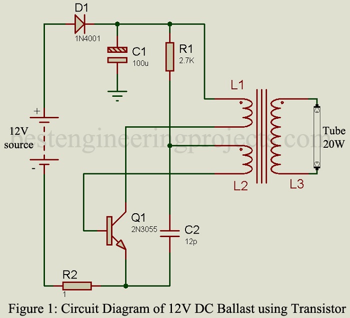
The project “12V DC Ballast” using power transistor 2N3055 is used to glow AC tube light using a DC source. The circuit of DC ballast is a DC-to-AC converter. DC ballast of various capacities (in watts) is already available in markets. The circuit posted here is of 20W capacity i.e. (it can drive a load up to 20 watts). Previously, we had posted Electronic Blast for Tube-light which drives load up to 40W, double the power of 12V DC Blast.
Circuit Description of 12V DC Ballast
The circuit of 12V DC Ballast uses very few components and is very simple to understand shown in Figure 1. As we have already stated the circuit posted here can glow up to 20W tube light efficiently.
When the power supply is given to the circuit base bias voltage is generated at the base of transistor T1 through resistor R1 and inductor L2. Similarly, the collector bias voltage is generated through inductor L1. When the transistor is on capacitor C2 with inductor L2 forms a tuned circuit. At the same time, L1 gets energized as a result electromagnetic energy is generated.
When the base voltage starts to increase the biasing voltage irregulates as a result transistor goes in off mode. When transistor T1 became off inductor L2 started to de-energize as a result back EMF produces on all three inductors L1, L2, and L3. This back EMF again turned on the transistor T1.
In this process of fast switching (ON and OFF) of the transistor, AC voltage is generated. The generated AC voltage is now stepped up in order to glow the Tube Light.
PARTS LIST OF 12V DC BALLAST
| Resistors (all ¼-watt, ± 5% Carbon) |
| R1 = 2.7 KΩ
R2 = 1Ω, 2 Watts |
| Capacitors |
| C1 = 100 µF/16V (Electrolytic Capacitor)
C2 = 0.01 µF (Ceramic Disc) |
| Semiconductors |
| T1 = 2N3055 (silicon NPN power transistor)
D1 = 1N4001 (General-Purpose Rectifier Diode) |
| Miscellaneous |
| L1 = 16 turns 22 SWG
L2 = 14 turns 33 SWG L3 = 250 turn 33 SWG Core = 7 cm Ferrite Core |

dear sir/ madam,
I was searching about this topic. it is great to read. you have mentioned, it will work up to 20watt. can this circuit drive an 11watt or 16watt tube? waiting for your reply.
Yes this circut can drive 11watt and/or 16watt tube.
can you please elaborate how the transistor works in the circuit
Sir I have tried this circuit and the circuit works well but the transistor gets very much heated , is it normal . Also the circuit draws 2.2 ampere . Is it ok , please let me know
The circuit is designed to support a maximum of a 20-watt tube light. To ensure proper functionality and prevent overheating, it is essential to use an appropriate heat sink with the transistor.