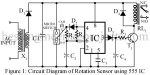
In this section, we discuss another application of the most popular IC, the 555 timers. Introduced in 1972 by the Signetics Corporation as a bipolar integrated circuit, the 555 is also available in CMOS technology and from several manufacturers. There are various projects we had already posted in the timer IC 555-based projects section. Now, we have come up with another interesting project called rotation sensor using the most popular IC of all time 555 Timer IC. When more conveyors or equipment are used in the processing system and anyone…
Read MoreCategory: Electronics Projects
Zener Diode Tester Circuit
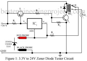
One of the most important uses of the zener diode is in making the constant voltage power supply. Its works are based on the fact that in the reverse breakdown (Zener) region, a small change in voltage across the zener diode produces a very large change in current through the circuit but the voltage across the Zener remains constant. In this article, we have posted two different circuits to test the zener diode i.e. general Zener diode tester circuit and modified Zener diode tester circuit Here, is a circuit that…
Read MoreDIY Strobe Light Circuit
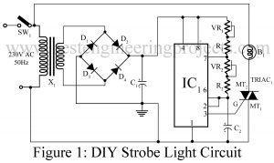
Here is one another application of one of the most versatile IC NE555, the DIY Strobe light circuit. A strobe light is also called a stroboscopic lamp and is used to produce a regular flash of light. The general strobe light has a very high flash energy of about 150 joules and very few milliseconds of discharge time. Due to this property, it emits flash power of several kilowatts. Various types of strobe light circuits using xenon flash lamps, flash tube, LEDs, etc. posted on bestengineeringprojects.com are listed below:- High Brightness…
Read MoreSimple Signal Injector Circuit
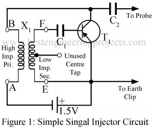
Here is a project of a Simple Signal Injector Circuit. Don’t think it’s just “another one”; see the advantages it offers over some other injectors: Commercial injectors working on 1.5V are rather large in size to be carried in a shirt pocket. You can carry this injector quite easily in a shirt pocket because the whole device can be assembled in a pencil cell holder. This circuit will give you a battery life of about two a single pencil cell. Most important of all, this injector will cost you at…
Read MoreEight Channel Audio Mixture with Multiple Control
Here is simple circuit of eight channel audio mixture with multiple control using IC TDA 1524A and 747 to mix eight individual sound. The PCB for soldering side and component side is also given. The conventional sound systems involved recording of sounds from several musical instruments, each played by different musicians using only a single microphone. Then, in order to balance the sound tone, they had to alter the positions of musicians according to the microphone. Due to which people started to record directly to stereo master tape. However that…
Read MoreLow Power Audio Amplifier Using LM386
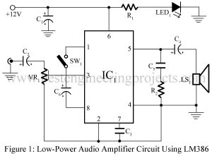
The circuit and PCB Design of Low Power Audio Amplifier using LM386 is posted here which used to drive at most audio power of 1 Watt. LM386 is an low voltage, battery operated power amplifier designed for application where low voltage is main concern. The main advantage of using LM386 is it does not requires any ground reference voltage and it’s output is automatically biased to 1/2 of supply voltage. Circuit Description of Low Power Audio Amplifier Using LM386 To derive at most audio power of 1 watt at the…
Read MoreRelay Tester Circuit
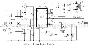
Here is the relay tester circuit using timer IC 555 which is used to measure pull-in and release voltage of relays ranging from 6V to 28V DC. Relays are probably the simplest electromechanical devices, yet they are the most important components of many industrial and domestic electrical equipment. All too often, it is a hardship for the equipment manufacturers to discover that the commercial quality relays of similar types have a wide range of operating voltage. Many times, it is found that the relay contacts will not close properly. Many…
Read MoreJFET Op-Amp Based Stereo Control Preamp
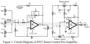
Almost all pre-amplifier circuit uses ordinary op-amp, which is not as good as JFET op-amp. JFET op-amp has very low noise and a very high input impedance due to which they can be used in a large number of circuits. The circuits are shown here fulfill the need for a handy, high-performance simple control preamp. Circuit Description of JFET Op-Amp Based Stereo Control Preamp Based on LF353N bi-FET op-amp the circuit is ideal for the stereo application for which quad LF347 or four LF351s can also be used is shown in…
Read MoreElectronics Thermometer Using Op-amp 741 IC
Here is the circuit diagram of an electronics thermometer using op-amp 741 IC and a silicon diode having a range of -20oC to 125oC. Various types of temperature measuring and controlling circuits either using a microcontroller or discrete component are already posted on bestengineeringprojects.com. Circuit Diagram of Electric Thermometer Using OP-AMP 741 The entire circuit of the electric thermometer is built around two op-amp 741 IC, a silicon diode, and a few passive components, where silicon diode D1 is used as a temperature sensor. The diode 4148 has a voltage…
Read MoreSingle Phasing Preventer Circuit
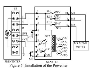
If we have been familiar with machinery, we all know how important it is to follow safety measures to mitigate injuries and accidents. A single phasing preventer circuit is one of the solutions we can look forward to. The phrase ‘preventer circuit’ itself portrays it. The single-phase preventer circuit is also a high low and unbalanced-supply voltage cut-off relay. To ensure complete safety for 3-phase machinery, the preventer circuit has been known to be handy. Generally, an induction motor burns out due to excessive voltage during an off-hour, a very…
Read More