Here is an electronic fuse using op-amp 741 which features slow-blow properties, a variable current limit, and a ‘live’ indication of its operation. Moreover, it is simple to restore. The electronic fuse using op-amp 741 allows the gadget to draw a higher current initially but keeps a watch on it. if the gadget continues to draw more current beyond the set time limit, it disconnects the supply. The fuse, therefore, acts as a cut-out and indicates this by a neon glow. It is replaced by simply resetting the circuit once.…
Read MoreCategory: Electronics Projects
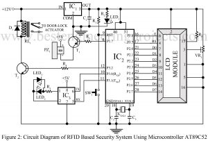
RFID Based Security System Using Microcontroller AT89C52
RFID Based Security System Using Microcontroller AT89C52 Different concepts of security systems have flourished along with different techniques and different types of equipment. RFID; Radio-Frequency identification (RFID) is another achievement we are relying on for optimum security facility in multiple projects. It makes use of electromagnetic fields to detect unique tags assigned to objects in the vicinity. There is a reason why it has mustered more popularity in comparison to other security systems that use bar codes and conventional methods. It is because RFID traces tags hidden inside objects, unlike…
Read MoreElectric guitar preamp circuit
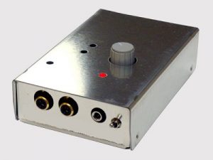
The entire circuit of the ‘Electric guitar preamp circuit’ is divided into small sections to ensure simplicity and easy understanding of the project. The first section comprises a single transistor that serves as a common-emitter amplifier. Be it in melodious songs or in rock songs, the guitar is an inseparable part of music in today’s world. To extend the level of sound such that it can be heard by every individual in a mass, amplifier circuits are extensively incorporated into the music system. And this circuit represents a similar concept.…
Read MoreFrequency Counter Schematic using Microcontroller AT89C51
Frequency Counter Schematic using Microcontroller AT89C51 is a simple yet mostly used frequency counter schematic used. The reason behind its simplicity also lies somewhere in the fact that this project uses only two components-AT89C2051 microcontrollers and a 16*2 LCD. Frequency is a crucial subject matter in every project. Precise and accurate frequency generation is another challenge we face in varieties of project design. As per the design of this project, this circuit can withstand frequency ranges between 1 Hz to ~16.5 Mhz, and the rest depends on the characteristics of…
Read MoreAC Motor Speed Controller Circuit Using AT89C51
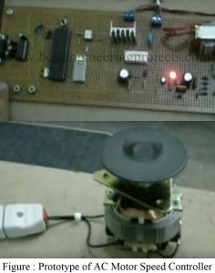
Here is a simple circuit “AC Motor Speed Controller Circuit Using Microcontroller” which is used to control the speed of AC motor using microcontroller At89c51. The circuit uses the principle of changing the firing angle of TRIAC to control the speed of the motor. Here, in this project, we had to use various switches to control the speed whereas an LED bar graph is used to indicate the speed of the motor. Circuit Description of AC Motor Speed Controller Circuit Using AT89C51 The circuit diagram of the signal phase AC…
Read MoreSound detector circuit using op-amp 741
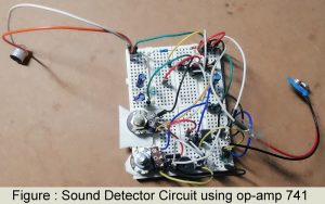
The circuit diagram of the sound detector circuit using op-amp 741 is shown in figure 1. The heart of the circuit is op-amp 741 which is used in order to sense the vibrations of sound waves condenser microphones. Introduction of Sound detector circuit using op-amp 741 Sometimes due to lack of concentration and our ignorance, we are unable to hear anything around us. And, that could lead to unfortunate misfortunes which could have been avoided with appropriate precautions. This circuit called ‘Sound Detector’ is what detects vibrations of the sound waves…
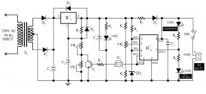
Read More12v, 7Ah Smart Battery Charger with PCB Diagram
Here is a 12V, 7Ah smart battery charger circuit which is also referred to as a smart charger uses three-stage of charging i.e. bulk stage, absorption stage, and float stage. Normal battery charger technology uses single-stage battery charging technology i.e. only charge the battery up to the maximum charging voltage preset by the charging circuit. Now here is a 12V, 7Ah smart battery charging circuit which is also referred to as a smart charger uses three-stage of charging i.e. bulk stage, absorption stage, and float stage. You may also like Arduino…
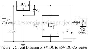
Read More9V DC to plus/minus 5V DC converter
Presented here is a simple circuit “9V DC to plus/minus 5V DC converter” that can convert a 9V battery to plus/minus 5V DC supply using LM7805 and ICL 7660. The operational amplifier requires a dual polarity power supply (+Ve and -Ve) because it has to swing on the output i.e. it does not swing into action during the negative cycle of signal if the negative source is not given. Thus, for the proper operation, we need a dual polarity power supply. Circuit Description of 9V DC to plus/minus 5V DC converter While…
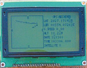
Read MoreGPS Navigator Circuit using ATmega 16
The system “GPS Navigator Circuit using ATmega 16” is implemented to detect the position/location of anything under consideration, and hence it is suited for navigation activities. Introduction to GPS Navigator Circuit using ATmega 16 The term GPS has been so popular in recent times. The credit for its quick recognition is due to the list of multiple features this system offers. Elaborated as a Global positioning system (GPS) it has already been established as a reliable technology that has made our lives much easier. Just with the involvement of GPS, we…
Read MoreGPS and GSM based Vehicle Tracking System
The project GPS and GSM-based Vehicle Tracking System uses Global Positioning System (GPS) and global system for mobile communication (GSM), which makes this project more economic than implementing a communication system through GPS satellites in a two-way GPS communication system. Introduction to GPS and GSM based Vehicle Tracking System Tracking has now been a recent trend followed everywhere. This process helps us to collect details and at the same time prevent robbery of devices being tracked. The project ‘GPS and GSM based Vehicle Tracking System’ which employs a microcontroller as its…
Read More
