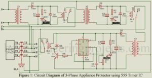
Three are two types of electrical/electronics appliances based on the main supply it requires. Generally, heavy electrical equipment requires a three-phase main supply for working. Three-phase mains supply has three different phases each are placed at 1200 angle with each other. In this post, you will learn how to design a three-phase power surge protector circuit using timer IC 555. A three-phase electrical appliance is expensive and requires all phase supplies, if voltage fluctuates or fails in any phase operation of the appliance may malfunction or become dead. In order…
Read MoreCategory: Electronics Projects
Best Audio Amplifier Circuit
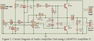
Electronics hobbyist love to design their own gadget which cam be used in our daily life. In the website Best Engineering Projects, we had published 100’s of such project which make life easy and sophisticated. In this post you will learn how to design your own Best audio amplifier circuit with premium specification. Specification of Best Audio Amplifier Circuits Output impedance of the circuit: 0.01Ω Frequency response i.e. working frequency: 20 Hz to 40 KHz Total harmonic distortion: 1.2% at 3W. Load or Speaker at output: 3Ω to 8Ω Description…
Read MoreFour Channel Audio Amplifier Circuit
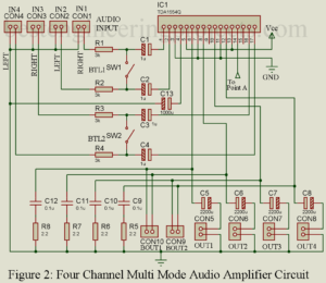
Single channel audio amplifier is readily available over internet, generally we combine multiple single channel amplifier in order to built multiple channel amplifier. But here in this post you will learn how to design four channel audio amplifier circuit using TDA1554Q IC. This type of circuit is very useful in sound lab, school, office etc. where we need multiple into and multiple output. Specification and Advantage of Four Channel Audio Amplifier Circuit Four input and four output port At load it provides 11W of power and at load it provide 6W…
Read MoreStereo Amplifier Circuit Diagram
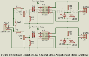
Stereo Amplifier Circuit Diagram we are going to design here is basically the combination of two mono audio amplifier. Portable and good audio amplifier is still a major concern to many electronic hobbyists and professional. People are still searching for good portable and battery-operated stereo amplifier. So, here in this article you will learn about designing of stereo amplifier using two audio amplifier IC. This stereo amplifier works with low voltage battery (4.5V, 6V) or even with a USB interface (+5V). In order to achieve above specification, we most design…
Read More10 Watt Audio Amplifier Circuit with Volume Control
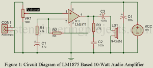
An amplifier that only amplify audio frequency range (typically 20Hz to 20K Hz) and attenuates all other range frequency range is called an audio amplifier. So, here in this post you will learn about power amplifier IC and at last we will design a 10-Watt Audio Amplifier Circuit with Volume Control using power amplifier IC with the features of volume control. We had already posted various amplifier circuit you may like. 7-Watt Audio Amplifier using TBA810 10-Watt Audio Amplifier using Transistor 20-Watt Audio Amplifier using TDA2020 20-Watt Audio Amplifier using…
Read MoreArduino Controlled 12V battery charger circuit
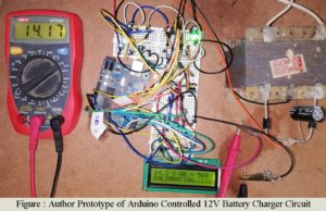
Arduino is an open-source that is designed for artists or for those who do not have an electronic background. Here, in this article, we are going to show you the method of making a battery charger circuit controlled using an Arduino uno board. The project Arduino Controlled 12V battery charger circuit is an advanced version of the previous posted project “12V, 7Ah Smart Battery Charger with PCB Diagram”. This charger also has the features of bulk stage charging and float stage charging as in the previous circuit. Silent features of…
Read MoreInterfacing of Unipolar and Bipolar Stepper Motor with Arduino
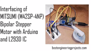
In this article we are going to interface unipolar and bipolar stepper motor and arduino using ULN2003 and L293D. The motor we are going to interface are MITSUMI M42SP-4NP stepping motor and 28BYJ-48 steeper motor Introduction Stepping motor | Interfacing of Unipolar and Bipolar Stepper Motor with Arduino An electric motor that rotates in a series of equal steps, each step controlled by a digital input signal, stepping motor are used in most electromechanical devices. Also called stepper motor. A stepper motor is an incremental motion machine i.e. the motor which…
Read MoreArduino Digital Clock using DS3231 Pi Module
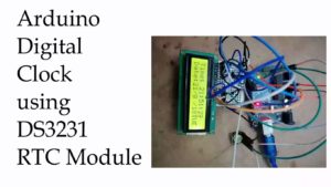
We are getting about how to make the digital clocks more accurate and precise even at varying parameters like temperature and humidity. Generally, in the market, if we go for buying the RTC module we will find the DS1307 module more simply. As DS1307 module is more prone to external temperature variation because it uses an external crystal oscillator circuit as a result the accuracy of the timekeeping changes. While designing a LED board for my college kec.edu.np, I suffered from a time accuracy problem. After a few days, time…
Read MoreDIY 5×3 matrix keypad for arduino
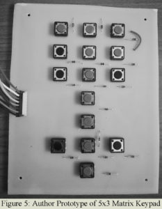
In this tutorial we are going to design a customized DIY 5×3 matrix keypad for arduino using tactile switch and small signal diode 1N4148. Many microcomputer/ Arduino system designs require some type of a keypad as an input device. Some time we required customized key for our own project rather then conventional available matrix keypad (4×4 or 4×3) in market. What if we require the key for other operation like left, right, up, down and ok operation. The outlook of the project may not be sophisticated if we had used…
Read MoreArduino Capacitance Meter Project
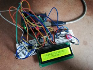
In this project you will learn how to make your own arduino capacitance meter (measure the value of capacitor from the range of pF to 1000’s uF). Generally, electronic hobbyist love to design their own gadget rather than buy. In this project we are using two approach for capacitance measurement i.e. charging and discharging approach arduino capacitance meter and multivibrator approach arduino capacitance meter. For measuring low value capacitor, we are using charging and discharging approach and for measuring high value capacitor we are using multivibrator approach. So, before starting…
Read More