In this project you will learn how to make your own arduino capacitance meter (measure the value of capacitor from the range of pF to 1000’s uF). Generally, electronic hobbyist love to design their own gadget rather than buy. In this project we are using two approach for capacitance measurement i.e. charging and discharging approach arduino capacitance meter and multivibrator approach arduino capacitance meter. For measuring low value capacitor, we are using charging and discharging approach and for measuring high value capacitor we are using multivibrator approach. So, before starting describing circuit let’s talk about few terminologies.
Capacitor: A capacitor stores electric energy in the form of electric field being established by the two polarities of charges on the two electrodes of a capacitor.
Capacitance: It is the capability of an element to store electric charge within it. Quantitatively capacitance is a measure of charge per unit voltage that can be stored in an element.
From the formula of capacitor, we found that energy stored by the capacitor is

From the equation we found that the voltage across the capacitor being constant, current through it is zero. This means that the capacitor, an application of d.c. voltage and with no initial charge first acts as short circuit but as soon as the full charge is retaining, the capacitor behaves an open circuit.
Circuit Description of Arduino Capacitance Meter
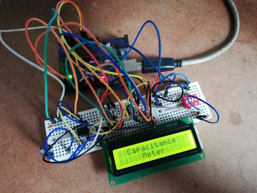
The circuit of arduino capacitance meter is shown in figure 1 and is build around arduino uno board, a LCD, a timer IC and few other electronic components like resistors, capacitors etc.
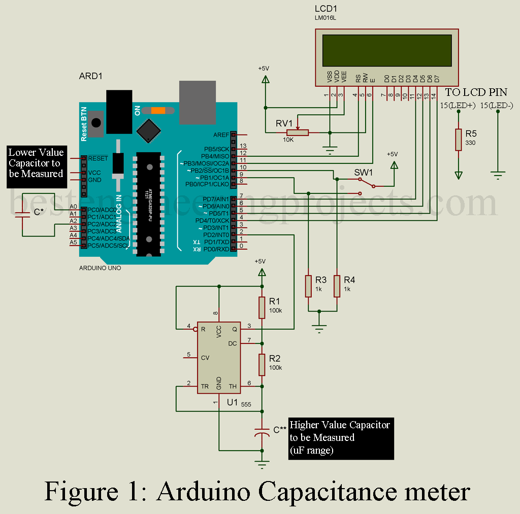
Circuit Connection Description of Arduino Capacitance Meter:
The purpose of using LCD is to display the value of capacitor. The LCD we are using here is of 16×2 alphanumeric type with 16 pins out. 8 Pins out of 16 pins are for data communication. Generally, LCD can be operated in two modes i.e. 8-bit mode and 4-bit mode. In 8-bit mode all the data pin (D0 – D7) is used for communication where in 4-bit mode only higher order data pin (D4 – D7) is used for communication. In the project Arduino Capacitance Meter uses 4-bit data mode. Pins D4 to D7 of LCD is connected to D7 to D4 pin of arduino uno respectively. Enable (E) and SET/RESET (RS) pin is connected to D11 and D12 pin of arduino uno board respectively.
Timer IC 555 is configured in astable multivibrator (Frequency Generator) mode and positive polarity of capacitor to be measured is connected to pin 2 of timer IC and negative polarity of capacitor is connected to ground. The output of timer IC from pin 3 is connected to D2 pin of arduino uno board. The capacitor of lower value generally in pF (Picco Farad) range is measured directly using analog pin using charging and discharging approach as shown in circuit diagram.
Working of Charging Discharging approach (used to measure lower value capacitance 1pF to 100nF).
In this approach the capacitor is first charged and discharged through known resistor. Time constant for a capacitor 
Where R = Fixed value of resistor used for charging and discharging of capacitor
C = Capacitance of capacitor
The time constant is defined as the time in which charge on the capacitor goes to 63.2% of the maximum value of charge.
The arduino uno board basically measure the time taken by the capacitor to reach the 63.2% of its voltage when it is fully charged and 36.8% of its voltage when it is fully discharged.
From the above expression we found that a resistor is required to charge and discharge the capacitor but in above circuit we are not using external resistor. This is because arduino board have internal pullup and pull-down resistor and capacitor is charged and discharged through this resistor. In this way we can measure capacitance of capacitor using charge and discharge approach.
Multivibrator Approach (Measure capacitor of range 1uF – 1000uF)
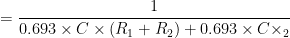
Capacitor of high value can be measured using this approach. The timer IC is used in astable mode. In this mode output swing between high and low at constant rate i.e. frequency is generated.
Mathematic involved in Arduino Capacitance Meter

Where R1 = resistor connected between Vcc and pin no 7 of Timer IC 555.
R2 = Resistor connected between pin 7 and pin 6 of timer IC

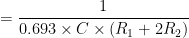
We know that


The value of resistor is fixed for arduino capacitance meter, two resistor each of 100K-ohm is used. When we insert any capacitor, a constant frequency is generated which is measured by arduino board in term of time. As arduino have inbuild time library function in milli-second.
Capacitance can be calculated in term of time
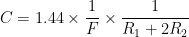
If we put the value of resistor in above expression it would look like
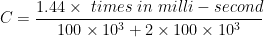

In this way we can calculate the capacitance of capacitor.
If the capacitor is of lower value the error become high in multivibrator approach so we are using charging and discharging approach for lower value of capacitor.
A single pole double throw switch is used to switch between measurement of higher value capacitor and lower value capacitor.
Software Code of Arduino Capacitance Meter: The Software code is written in arduino programming language and compiled in arduino programming language. You can download the code from below and use in your system without making any modification.
|
1 2 3 4 5 6 7 8 9 10 11 12 13 14 15 16 17 18 19 20 21 22 23 24 25 26 27 28 29 30 31 32 33 34 35 36 37 38 39 40 41 42 43 44 45 46 47 48 49 50 51 52 53 54 55 56 57 58 59 60 61 62 63 64 65 66 67 68 69 70 71 72 73 74 75 76 77 78 79 80 81 82 83 84 85 86 87 88 89 90 91 92 93 94 95 96 97 98 99 100 101 102 103 104 105 106 107 108 109 110 111 112 113 114 115 116 117 118 119 120 121 122 123 124 125 126 127 128 129 130 131 132 |
#include <LiquidCrystal.h> LiquidCrystal lcd(12, 11, 7, 6, 5, 4); volatile unsigned long microseconds; volatile float capacitance; int CapPf=9; int CapUf=10; const int Cap_Out = A2; const int Cap_In = A0; const float Stray_Cap = 24.48; const float Cap_GND = Stray_Cap; const float Pullup_Res = 34.8; const int ADC_Value = 1023; void setup() { lcd.begin(16, 2); pinMode(2,INPUT); pinMode(CapPf,INPUT); pinMode(CapUf,INPUT); pinMode(Cap_Out, OUTPUT); pinMode(Cap_In, OUTPUT); Serial.begin(9600); lcd.setCursor(0,0); lcd.print(" Capacitance "); lcd.setCursor(0,1); lcd.print(" Meter "); delay(2000); } void cap() { microseconds=micros()-microseconds; capacitance=1.443*microseconds/300; capacitance = capacitance/1000; Serial.print(capacitance,3); Serial.println("uF"); lcd.clear(); lcd.setCursor(0,0); lcd.print("Range: 1uf-1mF"); lcd.setCursor(0, 1); lcd.print(capacitance,3); lcd.print("uF "); microseconds=micros(); } void loop(){ if(digitalRead(CapUf)) { attachInterrupt(0,cap,RISING); } if(digitalRead(CapPf)) { lcd.clear(); pinMode(Cap_In, INPUT); digitalWrite(Cap_Out, HIGH); int val = analogRead(Cap_In); digitalWrite(Cap_Out, LOW); if (val < 1000) { pinMode(Cap_In, OUTPUT); float capacitance = (float)val * Cap_GND / (float)(ADC_Value - val); lcd.setCursor(0,0); lcd.print("Range: 1pF-1nF"); lcd.setCursor(0,1); lcd.print(capacitance,3); lcd.setCursor(14,1); lcd.print("pF"); delay(200); } else { pinMode(Cap_In, OUTPUT); delay(1); pinMode(Cap_Out, INPUT_PULLUP); unsigned long u1 = micros(); unsigned long t; int digVal; do { digVal = digitalRead(Cap_Out); unsigned long u2 = micros(); t = u2 > u1 ? u2 - u1 : u1 - u2; } while ((digVal < 1) && (t < 400000L)); pinMode(Cap_Out, INPUT); val = analogRead(Cap_Out); digitalWrite(Cap_In, HIGH); int dischargeTime = (int)(t / 1000L) * 5; delay(dischargeTime); pinMode(Cap_Out, OUTPUT); digitalWrite(Cap_Out, LOW); digitalWrite(Cap_In, LOW); float capacitance = -(float)t / Pullup_Res / log(1.0 - (float)val / (float)ADC_Value); lcd.setCursor(0,0); lcd.print("Scale: 1pF-1nF"); if (capacitance > 1000.0) { lcd.setCursor(0,1); lcd.print(capacitance / 1000.0, 2); lcd.setCursor(14,1); lcd.print("uF "); delay(200); } else { lcd.setCursor(0,1); lcd.print(capacitance); lcd.setCursor(14,1); lcd.print("nF"); delay(200); } } while (micros() % 1000 != 0); } } |