DIY Voltage to Frequency Converter Circuit

voltage to frequency converter circuit

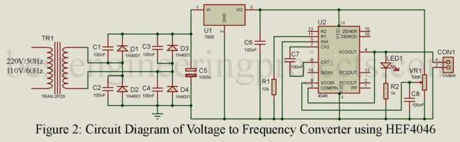
Voltage to Frequency Converter Circuit (VFC) is an electronic device that takes voltage as an input and generates a pulse train at a frequency proportional to the applied input voltage. A voltage to Frequency Converter can be regarded as a special type of Voltage-controlled Oscillator (VCO) designed to have a linear relationship between voltage and frequency over a wide range. VFC also provides low linearity error, temperature stability, and better performance than VCO. Applications of Voltage to Frequency Converter Circuit One of the applications of the VFC is the transmission…

Read More

Arduino Weighing Machine using HX711

arduino weighing machine

How to interface Load Cell with Arduino? How to make your very own Arduino Weighing Machine? Today, in this article you will learn about interfacing of Load Cell with Arduino and finally make your own Arduino Weighing Machine. This project is designed to weigh up to 50 Kg (depending upon the load cell you are using) accurately and efficiently. Components Required for Arduino Weighing Machine Arduino UNO Board x 1 16×2 Alphanumeric LCD x 1 Load Cell x 1 HX711 Module x 1 10K variable Resistor x 1 4.7K Resistor…

Read More

Battery Level Indicator

battery level indicator circuit

The circuit ‘Battery Level Indicator’ is simple, cheap, and compact. It can be used in emergency lights and other power supply circuits. We are using this simple circuit ‘battery level indicator’ for over a year and has found it works well in emergency light as well as battery charger circuit. We already indicate various battery voltage states using IC, this time we come with a little different concept and circuit for battery indication. Other battery level circuits posted in bestengineeringprojects.com Battery Status indicator Circuit 10 Level Battery Charge Indicator Circuit…

Read More

Audio Signal Tracer Schematic

dual audio signal tracer schematic

Signal transmission can be quite troublesome sometimes. To ensure that the signal is passed through a defined distance, here we have presented an “Audio Signal Tracer Schematic”.  As mentioned in the title; ‘Audio Signal Tracer Schematic’, this project is implemented to troubleshoot audio signals transmission in electronic circuits and radio, etc. It comprises two loudspeakers being Audio Signal Tracer and is packaged into a small hand-held test probe. The only power source required by the circuit is a battery and thus is more useful. Amplitude-modulated signals can also be detected…

Read More

Digital AC/DC Voltage cum Continuity Tester

Digital AC DC Voltage Cum Continuity Tester

The project “Digital AC/DC Voltage cum Continuity tester” can be used to test 25 Volts to 500 volts AC/DC voltage continuity and open-circuit condition by displaying on the 7-segment display. There is the various advantage of “Digital AC/DC Voltage cum Continuity tester” over multimeter are Small Size, low cost, easy operation and requires no troublesome selector switch to select testing mode. To make a selector switch free circuit, we had used 82K impedance for DC and 220K impedance for AC. The testing procedure is very simple all you have to…

Read More

Dual Trace Generator Circuit

dual trace generator using 555

A single beam CRO can be used for simultaneous display of two signals using this simple circuit “Dual Trace Generator Circuit”. The circuit uses one NE555 and two LM741 ICs, besides some passive components. The diode (1N4148) is used to get a 50 percent duty cycle. Circuit Description of Dual Trace Generator Circuit IC 555 is connected in astable mode and acts as a self-switching analog switch between the two signals to be displayed on the CRO. The output of IC 555 is given to the CRO. In order to…

Read More

Speaker Polarity Test Circuit

loud speaker polarity tester

These days, most BEP readers interested in Audio Engineering asked for a circuit that can recognize the polarity (positive and negative terminals) of the speaker. I had also experienced the problem of the polarity of speakers about a few years ago while testing one of my projects. At that time, I had used a multi-meter to test the polarity of the speaker. While testing a multi-meter you have to concentrate on the movement of the speaker cone which is a difficult job especially for a small speaker. For the large…

Read More

RJ45 Cable Tester Circuit

RJ45 cable tester using 555 IC

In the field of networking, RJ45 is the most common cable used. This cable consists of multiple wires clamped within a single plastic tube and in such a case, there is a high probability that the project implementing RJ45 will not work efficiently. Rather than isolating the entire circuit to check the fault, it is considered wiser to test the RJ45 cable which causes failure most of the time. And, here is the tester circuit called “RJ45 Cable Tester Circuit” which is used to test RJ45 cable either in straight-through…

Read More

Servo Motor Tester Circuit Using 555 IC

Servo motor tester circuit using 555

I believe testing circuits are a must for project geeks since these testers save so much time in debugging circuits. People invest all their efforts and spend so much time completing one project but most of the time they don’t get the desired output. There can be multiple reasons behind this and generally, it is because the components like servo motors are at fault. The project Servo Motor Tester Circuit Using 555 IC was used in the project after isolating it from the project and helping us to detect if…

Read More

Zener Diode Tester Circuit

modified circuit diagram of zener diode tester

One of the most important uses of the zener diode is in making the constant voltage power supply. Its works are based on the fact that in the reverse breakdown (Zener) region, a small change in voltage across the zener diode produces a very large change in current through the circuit but the voltage across the Zener remains constant. In this article, we have posted two different circuits to test the zener diode i.e. general Zener diode tester circuit and modified Zener diode tester circuit Here, is a circuit that…

Read More