Voltage to Frequency Converter Circuit (VFC) is an electronic device that takes voltage as an input and generates a pulse train at a frequency proportional to the applied input voltage. A voltage to Frequency Converter can be regarded as a special type of Voltage-controlled Oscillator (VCO) designed to have a linear relationship between voltage and frequency over a wide range. VFC also provides low linearity error, temperature stability, and better performance than VCO.
Applications of Voltage to Frequency Converter Circuit
One of the applications of the VFC is the transmission of analog signals over a long distance. Transmitting analog signals over a long distance is quite an arduous task. As analog signals are quite susceptible to noise and distortion and signal degrades over a long transmission line. Thus, VFCs are used to send signals at a frequency proportional to the input voltage and provide better signal quality with much lower interferences and noise at the receiver end than simply transmitting an analog signal.
Some other applications of VFC are listed below:
- In Phase-locked loops circuit
- Used in Frequency synthesizers
- In Analog to Digital conversion
- Waveform Generator circuit
- FM Modulation and PM modulation
- Telemetry system
- Temperature Meter
- FSK Modulators and Demodulators
- Tachometers
Now without any further delay let’s get into designing the simplest voltage-to-frequency converter but before we do so, we just need to know a little about the HEF4046B CMOS IC as the VFC circuit is built around it.
HEF4046B CMOS IC is a phase-locked loop circuit and one of its components is a linear voltage-controlled oscillator (VCO). Let us focus on the VCO components of the HEF4046B IC as we are designing a VFC. Input to VCO is provided at Pin 9 and output is taken through Pin 4. VCO requires an external capacitor (connected at Pins 6 and 7) and a resistor (connected at Pin 11) whose combination determines the frequency range of VCO. An optional external resistor can also be attached at Pin 12 which allows the VCO to have a frequency offset. The functional Diagram and Pin description of the IC are given below and for any more details about the IC refer to the datasheet.
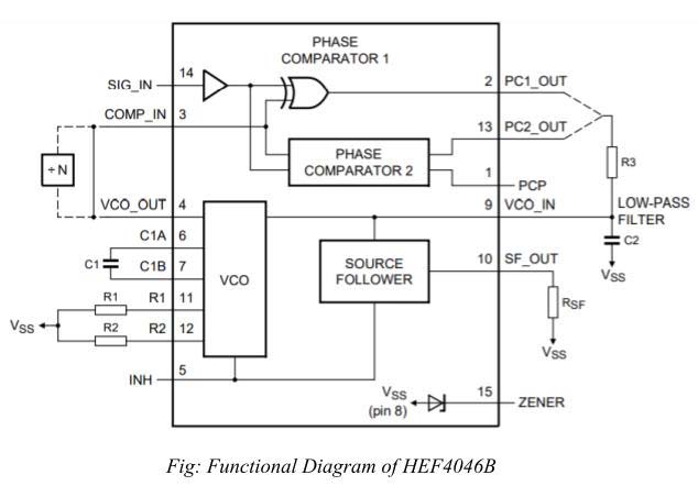
| Symbol | Pin | Description |
| PCP_OUT | 1 | Phase comparator pulse output |
| PC1_OUT | 2 | Phase comparator 1 output |
| COMP_IN | 3 | Comparator input |
| VCO_OUT | 4 | VCO input |
| INH | 5 | Inhibit output |
| C1A | 6 | Capacitor C1 connection A |
| C1B | 7 | Capacitor C1 connection B |
| VSS | 8 | Ground supply voltage |
| VCO_IN | 9 | VCO input |
| SF_OUT | 10 | Source-follower output |
| R1 | 11 | Resistor R1 connection |
| R2 | 12 | Resistor R2 connection |
| PC2_OUT | 13 | Phase comparator 2 output |
| SIG_IN | 14 | Signal input |
| ZENER | 15 | Zener diode input for regulated supply |
| VDD | 16 | Supply voltage |
Table: pin description of HEF4046B
Components Required for the Project
| Resistor (all ¼-watt, ± 1% Carbon Unless Stated Otherwise) |
| R1 = 10kΩ
R2 = 1kΩ VR1 =100 kΩ potmeter |
| Capacitors |
| C1 – C4, C6 – C8 = 100nF
C5 = 1000uF |
| Semiconductors |
| U1 = LM7805
U2 = HEF4046B phase-locked loop IC D1 – D4 = 1N4001 |
| Miscellaneous |
| LED1 = any color LED
CON1 = 2-pin connector TR1 = 220V/110V primary to 9V-0V, 350mA secondary output LDR1 = LDR GL5528* |
Circuit description of Voltage to Frequency Converter
The above figure describes the circuit diagram of the VFC circuit. The system is powered by the 5V DC-regulated power supply and is built around HEF4046B as a core component. As discussed earlier, the output frequency of the IC depends upon the combination of capacitor C7 and resistor R1. Here C7 = 100nF and R1 = 10KΩ which generates a square wave with a 50% duty cycle of frequency in the range of 0Hz – 1KHz. Also, we can add an optional offset resistor at Pin 12 and GND which allows the VCO to have a frequency offset whose value must be larger than the R1.
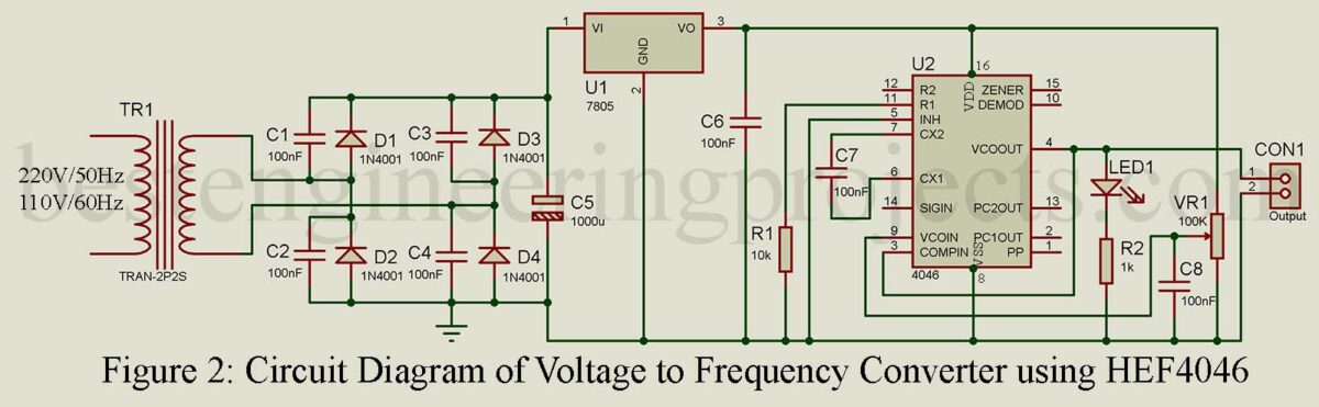
Here input to the VFC module is provided through the variable resistor where two fixed terminal is connected to the power supply pin i.e. 5V and GND as shown in the figure and the variable terminal is connected to input to the VCO of the IC. An additional Capacitor C2 is connected at Pin 9 to avoid any power-line interface and wild frequency fluctuation. Variable Resistor VR1 acts as a simple variable voltage source and by changing its value the output frequency can be varied in the range of 0 Hz to 1KHz.
Output is taken across the connector CON1 which is connected to the Pin 4 of the IC. Visual representation of the output signal being generated is presented by the LED1 connected across output Pin 4. Frequency output as observed in an oscilloscope is shown below.
LED1 and variable resistor VR1 are optional components.VR1 can be removed after the testing of the VFC module.
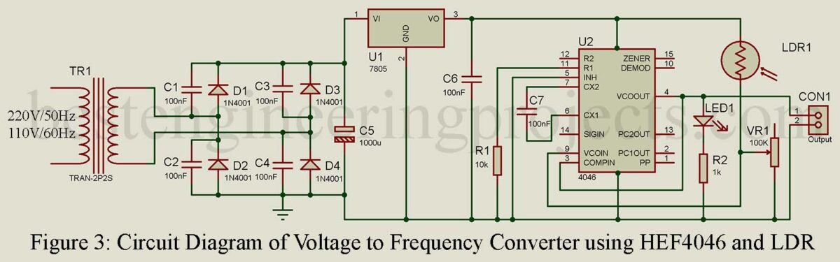
In the above VFC circuit, an LDR is connected to the input of VCO at pin 9 and it forms a potential divider with the variable resistor VR2. The output frequency is controlled by the analog sensor photoresistor LDR1 and depending upon the light intensity on the sensor frequency varies from 0 Hz (No light incident on LDR) to 1 KHz (Strong light incident on LDR). Here, the variable resistor can be replaced by a 100kΩ fixed resistor as it does not play a crucial role in determining the frequency.
5V Power Supply:
The input AC mains are stepped down to 9V using a step-down transformer TR1. This is now converted to DC using a bridge rectifier built using a general-purpose rectifier diode (D1 – D4). The rectified output is filtered using a 1000uF electrolytic capacitor and is given to the input terminal of a constant voltage regulator IC 7805 (U1). The constant 5V is achieved from the output terminal of U1 and is further passed through a 100nF capacitor in other to filter ripple if available. The capacitor across each bridge rectifier is connected to filter the ripple of AC mains.
Similarly, we can also use a thermistor instead of an LDR. In this case, the output frequency will depend upon the temperature.
The above-described VFC circuit is just a crude implementation and is done so to provide a simple understanding of how a VFC circuit works. Also, the IC HEF4046B used in the project is not a dedicated IC for the VFC operation. If you want to build an actual implementation of the VFC circuit, it is better to build with dedicated ICs like AD654, AD650, VFC32, LM231, LM331, etc.