Unexpected incidents occur in the road when the driver is unaware about certain activities that may lead to accidents in the vicinity. For instance, suppose you are on a trip with your family and driving along the narrow road, while you were in the middle of conversation, you notice car right at the front is driving backwards towards your car and in seconds is going to hit you.
It may be too late before you realize the situation. Maybe if you had known earlier, you could save yourself and your family from this disaster. This project serves the purpose right. The project entitled, ‘Car Reverse Horn’, notifies people around that the car is moving in the reverse direction with alarming sound and prevents any sort of misfortune.

Circuit Description of Car Reverse Horn:-
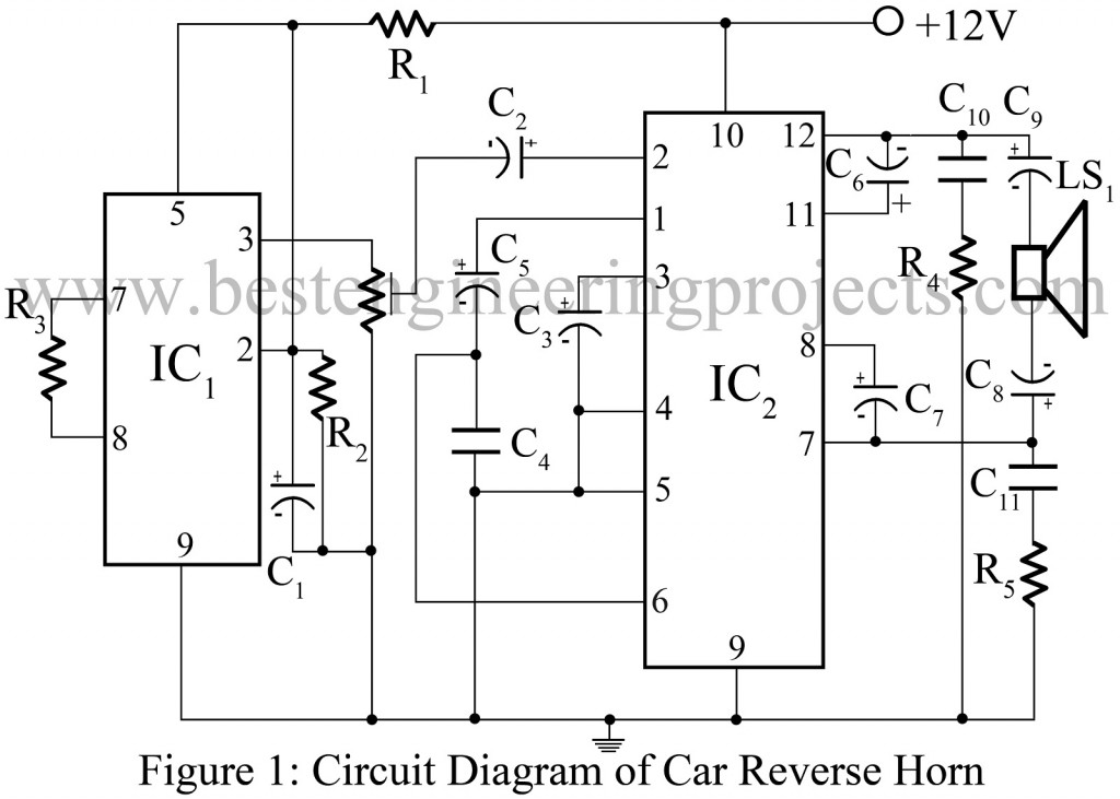
IC CTC2877 (IC1), also called melody generator IC is the major component of this circuit. It is followed by amplifier IC (IC2) and few other passive components. IC1 is made from a ROM oscillator and a pre-amplifier to generate sound. The sound output thus generated is available at pin 3 of IC which is further connected to pin 2 of amplifier IC through a variable resistor VR1.
The sound output supplied from IC1 to IC2 is amplified to a level desired and from respective pins (pin 7 and 12), the output is fed to loudspeaker through coupling capacitors C8 and C9 respectively. The fact that power supply required to operate this circuit can be obtained from battery of car, this circuit implementation becomes more feasible.
More automotive circuit posted in bestengineeringprojects.com
- Automobile Brake Failure Indicator
- Car Lock System using Arduino and GSM
- Arduino Based Car Reverse Alarm
- Automatic wiper for Automobile using Arduino and Rainsensor
- Car (Automobile) Battery Maintaining Circuit
- Beeper for Automobile Flasher Using 555
PARTS LIST OF CAR REVERSE HORN
Resistors (all ¼-watt, ± 5% Carbon)
R1 = 1.5 KΩ
R2 = 1 KΩ
R3 = 120 KΩ
R4, R5 = 1 Ω
Capacitors
C1 = 10 µF/25V (Electrolytic Capacitor)
C2 = 1 µF/25V (Electrolytic Capacitor)
C3 = 100 µF/25V (Electrolytic Capacitor)
C4 = 0.01 µF (Ceramic Disc)
C5, C6, C7 = 47 µF/25V (Electrolytic Capacitor)
C8, C9 = 470 µF/25V (Electrolytic Capacitor)
C10, C11 = 0.1 µF (Ceramic Disc)
Semiconductors
IC1 = CTC2877 (Melody Generator)
IC2 = AN7148 (Amplifier IC)
Miscellaneous
LS1 = 8 Ω loudspeaker
