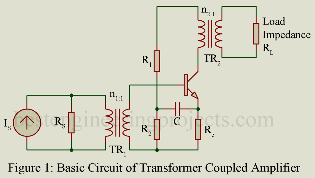
Figure 1 gives the basic circuit of a transformer coupled CE amplifier stage. In figure 1, a current source Is having shunt source resistance Rs drives the amplifier through a transformer TR1. Load resistance RL is fed from the collector output circuit through a transformer TR2. A transformer coupled CE amplifier finds following applications:
- As input stage of a multistage simplified and usually driven by a microphone.
- As output stage feeding the load impedance and
- As intermediate stage
Transformer coupling permits impedance matching thereby resulting in greater power gain. The transformer serves another function of isolating the collector circuit from the dc bias stabilization network of the next stage. For excellent performance, it is necessary to shield the transformer from electrical noise, hum and unwanted pick-ups.
In figure 1, capacitor C allows complete input power to flow into the base circuit. Resistor R1, R2 and Re taken together come in series with the primary of the output transformer TR2.
For maximum transfer of power from the driving source to the amplifier, the source resistance Rs is required to be matched with the input impedance of the amplifier transferred to the primary side of the input transformer TR1.
Thus, ….(1)
Similarly, for maximum transfer of power from the amplifier output circuit to the load impedance, the output impedance Z0 of the amplifier must be matched with the load impedance RL transferred to the primary side of the output transformer TR2.
Thus, …..(2)
In cascade amplifier using transistors, the input and output impedances of different stages will be different. Hence each transformer is required to be designed separately.
Analysis of Transformer Coupled CE Amplifier
As in the case of RC coupled amplifier, here also the entire frequency range may be divided into three frequency ranges namely (a) low frequency range (b) middle frequency range and (c) high frequency range. Figure 2 gives the equivalent circuit of one stage using high frequency hybrid- model for the transistor. Here shunt capacitance C in the input circuit indicates the total effective capacitance. Further, in figure 2,
represents the leakage inductance of the transformer TR1. Similarly
represents the leakage inductance of the transformer TR2 while
represent the magnetizing inductance. TR1 and TR2 represent ideal transformer.
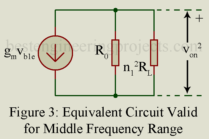
Middle Frequency Range
In the midband, frequency is so small that reactance of shunt capacitance C is very large. Hence C may be omitted. Similarly, the reactance of series inductances and
are so small that these may be neglected. Then the output circuit in the equivalent circuit of figure 3 reduce to that shown in figure 3. In this circuit, resistance R1 and R2 have also been neglected being small in the midband. Further the reactance of magnetising inductance
is large in comparison with the impedance R0 and
. Hence
is also neglected. Since, no reactive element is involved in the equivalent circuit of figure 2, the current gain and voltage gain remain constant in the midband.
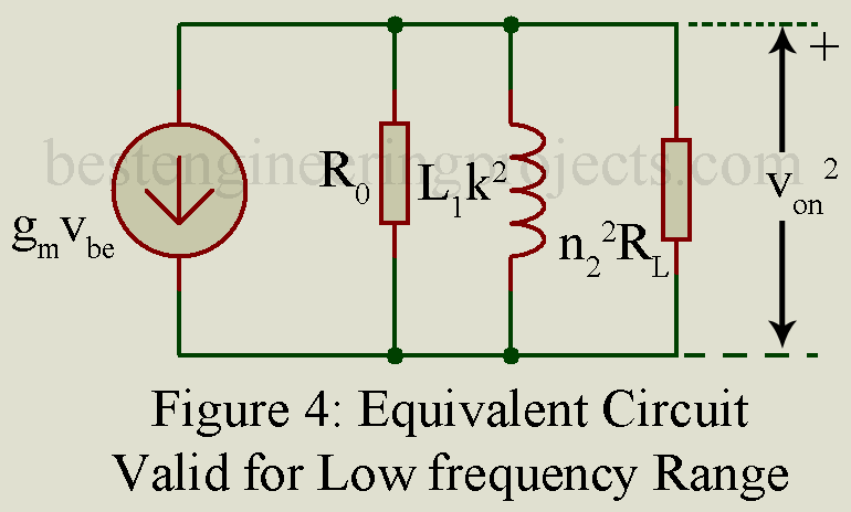
Low Frequency Range
In low frequency range, frequency being low, we may neglect the impedance R1’ and in the series path but we cannot neglect the impedance of magnetizing inductance
. Hence the equivalent circuit valid for low frequency range is as shown in figure 4.
Because of the presence of shunt inductance , the gain falls with the decrease of frequency.
The lower 3-dB frequency is then given by,
…..(3)
Where
And …..(4)
Hence,
In a typical case, and L = 10 henry.
Then
High Frequency Range
Figure 5 gives the input circuit of the equivalent circuit valid for high frequency range. Here leakage inductance has been transferred to the secondary side to result in inductance
. The magnetizing inductance has not been included in the equivalent circuit since its effect is negligible in high frequency range.
Now capacitance C resonates with inductance . But
being very low, the effect of this resonance is not of significance.
In the high frequency range, voltage across C reduces as the frequency increases. This time constant of the circuit equals
where
…..(5)
And under matched condition,
……(6)
The higher 3-dB frequency is given by,
…..(7)
Where L and R are given by Equations 5 and 6 respectively.
In a typical case, ,
,
,
and
Then Hence
In a typical case, resonance of shunt capacitance C and leakage inductance takes place at a frequency of about 20 KHz. But since Rb’c is small, effect of this resonance is not of much important.
Voltage gain versus frequency curve of transformer coupled CE amplifier is similar to that of RC coupled amplifier except for the possibility of slight increase in gain at the frequency of resonance. Transformer coupled amplifier is generally not used for intermediate stage in a cascade amplifier since it is costly and bulky. It is used as input stage and output stage where it can conveniently provide impedance matching.
You May Also like:


