In Class A amplifier the input signal is reproduced, increased in amplitude, in exactly the same wave shapes at the output. To achieve this, the quiescent point (Q) is at the center of the collector current (IC) curve, so that the input signal as well as the amplitude output signal operates only over the linear portion of this curve. IC flows at all times. Class A amplifiers are used whenever the output wave shape must be the same, with a minimum of distortion, as the input signal. Operational amplifiers, and…
Search Results for: audio amplifier
Stereo Amplifier Circuit Diagram
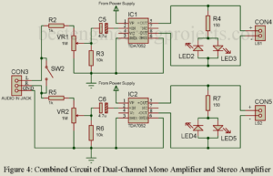
Stereo Amplifier Circuit Diagram we are going to design here is basically the combination of two mono audio amplifier. Portable and good audio amplifier is still a major concern to many electronic hobbyists and professional. People are still searching for good portable and battery-operated stereo amplifier. So, here in this article you will learn about designing of stereo amplifier using two audio amplifier IC. This stereo amplifier works with low voltage battery (4.5V, 6V) or even with a USB interface (+5V). In order to achieve above specification, we most design…
Class B Push Pull Amplifier
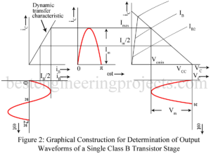
In class B push pull amplifier, output current (collector current) flows for only half the cycle of the input signal. Hence distortion is excessive. Single ended operation is, therefore, not possible in class B audio amplifier. Class B audio (un-tuned) amplifier must necessarily use push pull operation to reduce distortion. In effect, in class B push pull amplifier, one transistor say Q1 conduct during one half cycle while the other transistor namely Q2 conducts during the other half cycle. Class A power amplifiers may use either single ended or push…
Maximum Collector Efficiency of Class A Amplifier
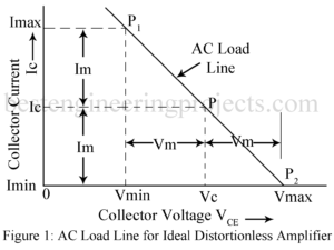
Maximum Collector Circuit Efficiency of Class A Amplifier Conversion Efficiency An amplifier draws a.c. power from dc supply (collector supply VCC in CE amplifier) and converts a part of it into useful a.c. power delivered to the load impedance. The ratio of the a.c. output power to the d.c. power from the supply source in the output is called the conversion efficiency, also called collector circuit efficiency in the case of CE amplifier and is denoted by Greek letter . Thus, ……(1) For present analysis, we assume a resistance…
Cascading of Amplifier Stages
What is Cascading of Amplifier Stages? A single stage of amplifier can provide only a limited current gain or voltage gain. Most of the applications require much higher gain. Hence, we usually use several amplifier stages connected in cascade i.e. connected such that the output of one stage becomes the input to the next stage. Thus, a multistage amplifier or cascade amplifier may provide a higher voltage gain or current gain. Cascading of amplifier stages is usually done to increase the total gain of the amplifier. However, sometimes cascading is…
Classification of Amplifiers
Amplifiers may be classified or Classification of Amplifiers in several ways as described below: According to the Frequency Range | Classification of Amplifiers Thus amplifiers may be classified as below: DC (Direct coupled) Amplifiers from zero frequency (dc) onwards. Audio Frequency Amplifiers 20 Hz to 20 KHz Video Frequency Amplifiers up-to a few MHz. Radio Frequency (RF) Amplifiers from a few KHz to hundreds of MHz. Ultra-high Frequency (UHF) and Microwave Amplifier up-to hundred or thousands of MHz. According to the method of operation | Classification of Amplifiers The position of the…
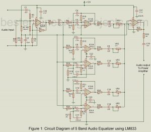
5 Band Audio Equalizer Circuit using LM833
Today in this article we are going to show you the circuit diagram and description of the 5 Band Audio Equalizer Circuit using LM833. We already control 8W + 8W Stereo with a graphic equalizer, but this time we come with 5 Band Audio Equalizer Circuit. First, let’s talk about what an equalizer is. 5 Band Audio Equalizer Circuits using LM833 Equalizer circuits are those circuits that are responsible to maintain a balance between the frequency components. The project 5 Band Audio Equalizer Circuit using LM833 divides the audio spectrum…
Audio Oscillators
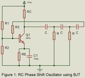
RC oscillators are principally used for generating audio frequencies. Two popularly used RC oscillators are (i) RC phase shift oscillator using either BJT or FET and (ii) Wien Bridge oscillator. Another popularly used audio oscillator is the Beat Frequency Oscillator (BFO). We here consider these three audio oscillators. RC Phase Shift Oscillator using BJT. Figure 1 gives the basic circuit. It is a sinewave feedback oscillator and uses an amplifier followed by three section R-C phase shift network. Output of the last section is fed to the base. We assume…
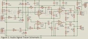
Audio Signal Tracer Schematic
Signal transmission can be quite troublesome sometimes. To ensure that the signal is passed through a defined distance, here we have presented an “Audio Signal Tracer Schematic”. As mentioned in the title; ‘Audio Signal Tracer Schematic’, this project is implemented to troubleshoot audio signals transmission in electronic circuits and radio, etc. It comprises two loudspeakers being Audio Signal Tracer and is packaged into a small hand-held test probe. The only power source required by the circuit is a battery and thus is more useful. Amplitude-modulated signals can also be detected…
Eight Channel Audio Mixture with Multiple Control
Here is simple circuit of eight channel audio mixture with multiple control using IC TDA 1524A and 747 to mix eight individual sound. The PCB for soldering side and component side is also given. The conventional sound systems involved recording of sounds from several musical instruments, each played by different musicians using only a single microphone. Then, in order to balance the sound tone, they had to alter the positions of musicians according to the microphone. Due to which people started to record directly to stereo master tape. However that…
