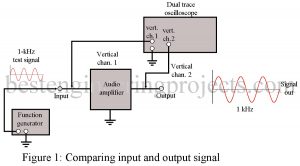
When traveling uncharted roads, having a map can make the difference between getting lost and finding your way. A plan for troubleshooting, like a map, can help guide you to an equipment malfunction. Made up of a logical sequence of troubleshooting steps, this troubleshooting map can help the technician hunt down the defect in a piece of electronic communication equipment. By developing and using this strategy, the technician can become very proficient at locating electronic problems and repairing them. After completing this article, you should be able to Describe the…
Read MoreRF Amplifier Troubleshooting
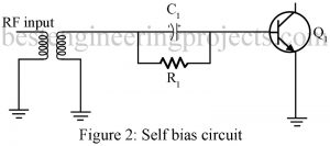
How to? RF Amplifier Troubleshooting BIAS SUPPLY Many RF amplifiers utilize power from the previous stage to provide dc bias. Figure 2 shows how bias for the transistor Q1 is developed. RF from the previous stage is rectified by the base-emitter junction of Q1. The current flows through R1 and the transformer to ground. The reactance of C1 is low at RF, so the RF bypasses the resistor. C1 also serves to filter the RF pulses and develop a dc voltage across R1. At the base of Q1, this dc…
Read MoreDual Polarity 5v from 9v Battery
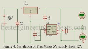
Almost all electronic devices used in electronic circuits need a dc source of power to operate. The source of dc power is used to establish the dc operating point for the passive and active electronic devices in-corporate in the system. This day almost all circuits 5V regulated power supply but an operational amplifier requires a dual power supply (positive and negative) for proper operation, while we are using the battery power supply for a circuit then it would be difficult to get a dual polarity power supply. In order to…
Read MoreElectronics Troubleshooting Techniques
Introduction to Electronics Troubleshooting Techniques Due to the increasing complexity of electronic communications equipment, the technician must have a good understanding of communication circuits and concepts. To be an effective troubleshooter, the technician must also be able to quickly isolate faulty components and repair the defective circuit. Recognizing the way, a circuit may malfunction is a key factor to speedy repair procedures. After completing this tutorial on electronics troubleshooting techniques, you should be able to Explain general troubleshooting techniques Recognize major types of circuit failures List the four troubleshooting techniques…
Read MoreSimple Battery Changeover Relay
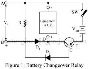
It is economical to use a battery eliminator but with frequent power failure in most developing countries, it becomes annoying to change over from battery eliminator to battery operation every time the electric supply fails. Thus, we had designed a simple battery changeover relay. A simple way to avoid the nuisance is by connecting the battery and power pack in parallel. But the advantage with such a system is that when the eliminator voltage falls, even slightly (say from 6V to 5V), though the performance of the set remains unaffected,…
Read MoreWireless Temperature and Humidity Indicator for Fridge
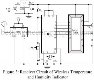
There are various types of circuit used to indicate the temperature and humidity of fridge but it cannot measure relative humidity accurately. Because at the time of door opening of fridge relative humidity will rise or fall due to moister of surrounding. Thus, we had posted here “Wireless Temperature and Humidity Indicator for Fridge”. Here, we had posted a simple, small and handy wireless device which is used to measure temperature, humidity and relative humidity from inside the fridge. The circuit posted here used RF technology to transmit and receive…
Read MoreRotation Sensor using 555 IC
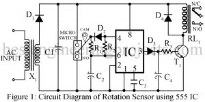
In this section, we discuss another application of the most popular IC, the 555 timers. Introduced in 1972 by the Signetics Corporation as a bipolar integrated circuit, the 555 is also available in CMOS technology and from several manufacturers. There are various projects we had already posted in the timer IC 555-based projects section. Now, we have come up with another interesting project called rotation sensor using the most popular IC of all time 555 Timer IC. When more conveyors or equipment are used in the processing system and anyone…
Read MoreZener Diode Tester Circuit
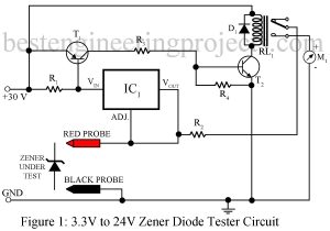
One of the most important uses of the zener diode is in making the constant voltage power supply. Its works are based on the fact that in the reverse breakdown (Zener) region, a small change in voltage across the zener diode produces a very large change in current through the circuit but the voltage across the Zener remains constant. In this article, we have posted two different circuits to test the zener diode i.e. general Zener diode tester circuit and modified Zener diode tester circuit Here, is a circuit that…
Read MoreDIY Strobe Light Circuit
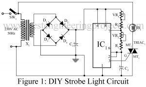
Here is one another application of one of the most versatile IC NE555, the DIY Strobe light circuit. A strobe light is also called a stroboscopic lamp and is used to produce a regular flash of light. The general strobe light has a very high flash energy of about 150 joules and very few milliseconds of discharge time. Due to this property, it emits flash power of several kilowatts. Various types of strobe light circuits using xenon flash lamps, flash tube, LEDs, etc. posted on bestengineeringprojects.com are listed below:- High Brightness…
Read MoreSimple Signal Injector Circuit
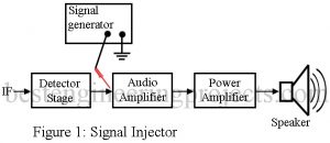
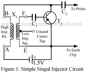
Here is a project of a Simple Signal Injector Circuit. Don’t think it’s just “another one”; see the advantages it offers over some other injectors: Commercial injectors working on 1.5V are rather large in size to be carried in a shirt pocket. You can carry this injector quite easily in a shirt pocket because the whole device can be assembled in a pencil cell holder. This circuit will give you a battery life of about two a single pencil cell. Most important of all, this injector will cost you at…
Read More