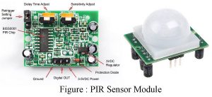
People are always in rush these days and they forget important things like turning the lights off in addition to a few other electrical devices. This results in either an electrical explosion or wastage of power. And, so to eradicate such issues, we have developed a Power Saver Circuit Diagram based on a Passive infrared sensor that employs a PIR motion sensor to detect the presence of human beings and as they leave the room, turn any electrical appliances connected to the circuit after a certain defined time interval. The…
Read MoreMini Projects using IC 741
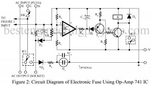
Here in this post, we have compiled some of the verified mini projects using IC 741. The mini-projects using IC 741 listed here can be used as diploma-level as well as high school-level projects. List of Mini Projects using IC 741 1. Electronics Thermometer Using Op-amp 741 IC Here is the circuit diagram of an electronics thermometer using an operational amplifier and silicon diode having a range of -20oC to 125oC.2. Electronic Fuse Using Op-amp 741 Here is an electronic fuse using op-amp 741 which features slow-blow properties, a…
Read MoreAudio Amplifier Circuit Using 555 IC
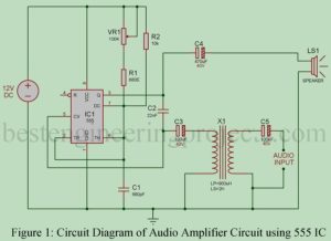
As being electronics hobbyists we all know about timer IC 555. Timer IC 555 is one of the most popular IC of all time because of its application. This IC has various applications like clock pulse generator, time delay circuit, etc. Here, is another application of 555 timer IC i.e. Audio Amplifier using 555. We are going to use a 555 timer IC rather than a conventional amplifier IC because it has unique features like low audio distortion and high efficiency with a high base. PWM is the method by…
Read MoreRJ45 Cable Tester Circuit
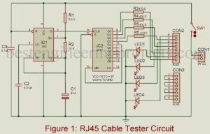
In the field of networking, RJ45 is the most common cable used. This cable consists of multiple wires clamped within a single plastic tube and in such a case, there is a high probability that the project implementing RJ45 will not work efficiently. Rather than isolating the entire circuit to check the fault, it is considered wiser to test the RJ45 cable which causes failure most of the time. And, here is the tester circuit called “RJ45 Cable Tester Circuit” which is used to test RJ45 cable either in straight-through…
Read MoreAC Voltage Stabilizer Circuit using 556 IC
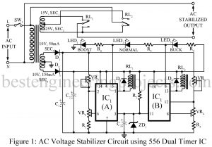
AC Voltage Stabilizer Circuit using 556 IC Various types of AC voltage stabilizer circuits had already been posted on bestengineeringprojects.com like Versatile Auto Cut-off Unit Automatic Voltage Stabilizer Circuit Overvoltage Protection Circuit The circuit posted here is a cheap, versatile, and high-performance AC voltage stabilizer using dual timer IC 556 IC. The circuit makes use of most of the features of dual timer IC 556, namely, the four voltage level comparators, two high current sourcing/sinking outputs, two discharge transistors, and the ability to provide hysteresis with the help of its…
Read MoreServo Motor Tester Circuit Using 555 IC
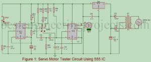
I believe testing circuits are a must for project geeks since these testers save so much time in debugging circuits. People invest all their efforts and spend so much time completing one project but most of the time they don’t get the desired output. There can be multiple reasons behind this and generally, it is because the components like servo motors are at fault. The project Servo Motor Tester Circuit Using 555 IC was used in the project after isolating it from the project and helping us to detect if…
Read MoreBLDC Motor Driver Circuit
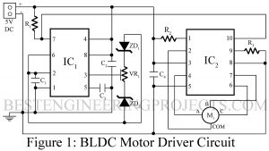
After the BLDC motor driver circuit, had been introduced, its demand and use have increased past the mid- 20th century. Be it because of its flexibility that it can be converted into small size, or is it because it is much lighter than the conventional dc motor with brushes, the product is in the most preferred list of people. The device demands information about the rotor- position to set the favorable commutation angle. And, for this purpose, a Hall effect sensor is employed in the project. However, doing so can…
Read MoreListening Bug Circuit using op-amp LM386
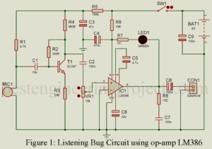
Listening bug? What is that? Is it what strikes your head, the first time you see this title? Well, allow us to clear your confusion. Listening bug is a resemblance to that concept improves the quality of sound we hear. Input sound collected by the condenser microphone with high-sensitivity is supplied to the Listening Bug Circuit and adjustable sound gain is obtained at its output which improves the quality of sound for obvious reasons. Now, people can hear everything smoothly without risk of interruption and no talks will be missed.…
Read MoreCar (Automobile) Battery Maintaining Circuit
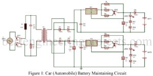
Here is a simple circuit built around very common electronics components easily available in the local market which is used to protect car (automobile) batteries from deep discharge and also protect from getting damaged. Let’s get some facts about automobile batteries. We all know that battery itself has some self-discharge rate which depends upon battery capacity and the materials used to make it. Various reasons discharge a battery like an electrical installation in a car. When we do not use our automobile for a longer period the battery becomes fully…
Read MoreDIY Hearing Aid Circuit using 555
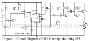
The general circuit of Hearing Aid available over the internet used a normal transistorize circuit thus it consumes more power. So, here we are concentrated to design a circuit that consumes less power, DIY Hearing Aid Circuit using 555. For that, the circuit present here of DIY Hearing Aid Using 555 has an automatic triggering mode which consumes 96 mA at the time of amplifier trigger or you can say when sound is detected else it consumes only 6 mA which is very less. Other than less power consumption the…
Read More