People are always in rush these days and they forget important things like turning the lights off in addition to a few other electrical devices. This results in either an electrical explosion or wastage of power. And, so to eradicate such issues, we have developed a Power Saver Circuit Diagram based on a Passive infrared sensor that employs a PIR motion sensor to detect the presence of human beings and as they leave the room, turn any electrical appliances connected to the circuit after a certain defined time interval. The circuit works automatically and turns the lights once anyone enters the room and thus saving human effort as well as saving power.
Circuit Description of Power Saver Circuit Diagram using PIR
In figure 1, the entire circuit of the power saver circuit diagram is shown. The Power Saver Circuit Diagram comprises various popular and easy available electronics parts like a bridge rectifier (which can be built using four general-purpose rectifier diodes, but for simplicity, we had used DB107), PIR motion sensor (used to detect the presence of human), timer NE555 (used as time delay), two 1N4007 rectifier diodes (D1 and D2) and few other components.
As we said earlier, the PIR sensor used in this circuit monitor infrared radiation continuously and it is obstructed by the presence of people either while leaving or entering the room. That is when the sensor detects the presence of people. As the radiation pattern of the sensor changes, it outputs a high signal output of 3.3V which is further amplified using transistor T1 and given to the trigger pin (pin 2) and threshold pin (6) of Timer IC as shown in the power saver circuit diagram.
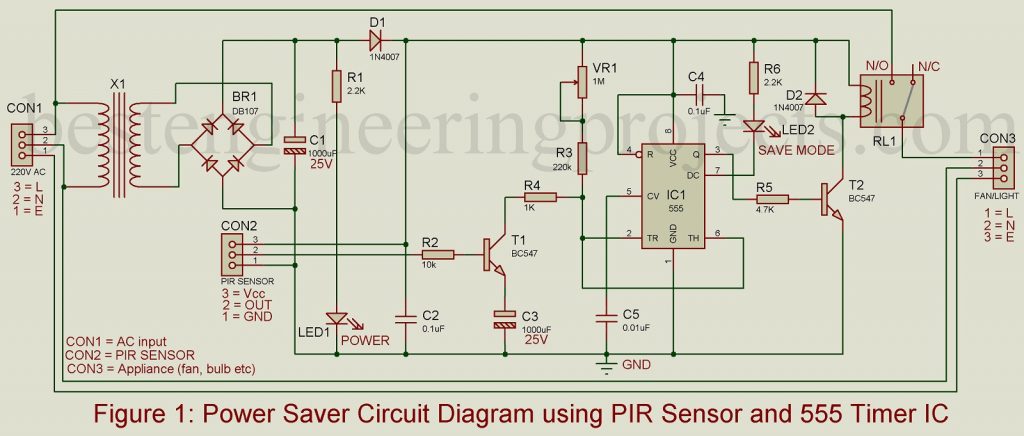
PIR sensor has a small-time span (continuously monitoring) which can be increased as per our requirements. As we listed above, timer IC NE555 with resistor R3, potmeter VR1, and capacitor C3 act as time delay circuits. The output from pin 3 of IC1 is fed to relay driver transistor T2 which controls relay RL1. As we know a relay is an electromechanical switch that is used to control electrical appliances i.e. lights, fans, etc.
For the power source, a 230V AC mains power is given to the connector CON1 as shown in the power saver circuit diagram. The step-down transformer X1 is used to lower the input AC voltage (220V) to 9V. The lower AC voltage is converted to pulsating DC using a bridge rectifier circuit and further connected across a capacitor for smoothening pulsating DC. The output DC voltage is indicated by LED1.
Working Description of Power Saver Circuit Diagram using PIR and 555 IC
In the first phase, the variable resistor VR1 with resistor R3 charges capacitor C3 as soon as the circuit operates. At that point, IC1 offers voltages at ports 2 and 6 which is two-thirds of the voltage supply i.e. (2/3 Vcc) of IC. Due to this, the output at pin 3 goes high and that triggers the relay through transistor T2 finally, the appliance connected to the circuit starts working as a prototype.
However, when the capacitor C3 achieves two-thirds of the supply voltage and continues to get charged, output at pin 3 of IC1 goes low to de-energies the relay, and hence the switches controlling the appliance are turned off after a certain predefined delay as set through potmeter VR1.

Once the circuit is triggered, the PIR sensor gets activated and starts to check for any unusual changes in the radiation pattern. When it finds any blockage or motion, the output pin of PIR goes high which is approximately 3.3V for the defined period. That high output is then fed as input to the transistor T1. As a result, the capacitor C3 gets discharged through resistor R4. The cycle continues once the capacitor voltage falls below two-thirds of the power supply and the appliances connected to the circuit start to operate.
The power-save mode of the circuit is reflected by the glowing LED2 once the appliances are switched off.
Check out other Infrared (IR) based projects posted on bestengineeringprojects.com
- Infrared Remote Controller Using Arduino
- Proximity Detector Circuit Using 555 timer IC
- IR Remote Controller Fan Regulator using AT89C2051
- DIY Opto Reflector Sensor using 555
- Universal Arduino IR Receiver Circuit
Construction and Testing of Power Saver Circuit Diagram of PIR and 555 IC
Two figures; figure 2 and figure 3 represent the solder side PCB layout for the infrared sensor-based power saver circuit and its component side PCB layout respectively. Talking about the circuit arrangement, it is preferred to keep the PCB in a small enclosure. There must be enough space to connect a 230V AC input to CON1 and a light/fan to CON3 at the back part of the enclosure. Use a 3-wire cable to connect the PIR sensor to PCB at CON2 and then place the device at the desired place.
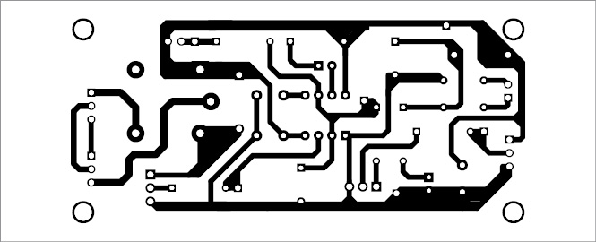
Figure 2: Solder Side PCB of Power Saver Circuit Diagram
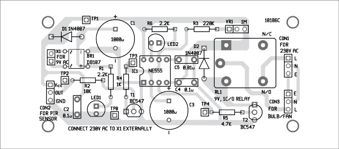
Figure 3: Components Side PCB of Power Saver Circuit Diagram
To ensure better sensing, the PIR motion sensor must be first checked thoroughly. And, so connect two pins; Vcc and GND of the sensor to a 9V (or 12V) battery. In doing so, keep an eye on the output voltage corresponding to the ground by waving your hand in front of the sensor. The factors like sensitivity and time controls of the PIR sensor can be adjusted as suited for the project. To obtain maximum sensitivity and time signal, turn both presets clockwise. For better sensing, the dome surface (oval surface) of the PIR should be clean.
When the testing procedure of the PIR sensor is completed, isolate the PIR sensor from the battery and then fix it to the PCB. After this, assemble all other components on the PCB using terminal connectors CON1 and CON3 for input and output respectively.
Click Here to Download PCB of Power Saver Circuit Diagram
Initially, the LED2 must be at off state and the relay should be energized. And, later the LED2 starts to glow and the relay is now de-energized indicating that the circuit is off.
PARTS LIST OF POWER SAVER CIRCUIT DIAGRAM USING PIR AND 555 IC
| Resistor (all ¼-watt, ± 5% Carbon) |
| R1, R6 = 22 KΩ
R2 = 10 KΩ R3 = 220 KΩ R4 = 1 KΩ R5 = 4.7 KΩ VR1 = 1 MΩ POT. |
| Capacitors |
| C1, C3 = 1000 µF, 25V (Electrolytic Capacitor)
C2, C4 = 0.1 µF (Ceramic Disc) C5 = 0.01 µF (Ceramic Disc) |
| Semiconductors |
| IC1 = NE555 (Timer IC)
T1, T2 = BC547 (NPN Transistor) D1, D2 = 1N4007 (Rectifier Diode) BR1 = DB107 (Bridge Rectifier) LED1, LED2 = 5mm any Color LED |
| Miscellaneous |
| PIR Sensor Module
X1 = 230v ac primary to 9v, 300mA Secondary Transformer RL1 = 9v, 1C/O relay CON1 – CON3 = 3-pin Connector |