How to? RF Amplifier Troubleshooting
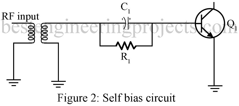
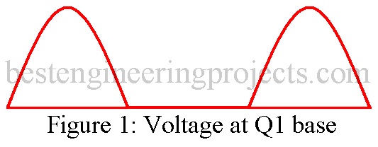
- BIAS SUPPLY Many RF amplifiers utilize power from the previous stage to provide dc bias. Figure 2 shows how bias for the transistor Q1 is developed. RF from the previous stage is rectified by the base-emitter junction of Q1. The current flows through R1 and the transformer to ground. The reactance of C1 is low at RF, so the RF bypasses the resistor. C1 also serves to filter the RF pulses and develop a dc voltage across R1. At the base of Q1, this dc voltage is negative with respect to ground. Therefore, Q1 will be a class C amplifier conducting only on positive RF peaks. Figure 1 shows the instantaneous voltage at the base of Q1 that you can observe with an oscilloscope.

- SHORTED Cl If C1 were to short, excessive drive would reach Q1. No negative bias for Q1 could be developed. This would cause Q1 to draw excessive current and destroy itself. If Q1 is bad, always check all components ahead of Q1 before replacing it.
- OPEN Cl If C1 were open, the drive reaching Q1 would be greatly reduced. Bias voltage would below and Q1 would not develop full power output.
- OPEN R1 Resistors in these circuits may overheat and fail open. C1 will charge to the negative peak of the RF drive voltage due to the rectifier action of the base-emitter junction. This will cut Q1 off and there will be no power output.
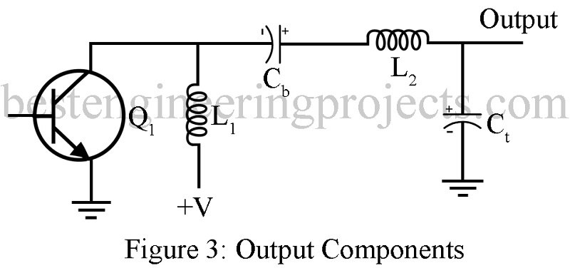
- OUTPUT NETWORK Now consider possible faults in components on the output side of Q1. Common faults are shorted blocking capacitors, overheated tuning capacitors, and open chokes.
- SHORTED BLOCKING CAPACITOR Consider the circuit in Fig. 3. Assume that capacitor Cb has shorted. If this amplifier is connected to an antenna that is not dc grounded, there will be no effect at all. Cb is not part of any tuning circuit; its job is to block the dc power supply from the succeeding stage or antenna.
Many antennas show a short circuit to dc. In this case, excessive current would flow through L1 and L2, possibly damaging them and the power supply. If a shorted blocking capacitor is found, it is wise to check for damage to the wiring or printed circuit board and the power supply.
- FAULTY TUNING CAPACITOR The ac load impedance presented to the transistor Q1 is dependent on Ct and L2 forming a tuned circuit that transforms the antenna impedance to the correct value. Assume that Ct is shorted. In this case, the load impedance would probably be too low and the Q1 would draw excessive current. If Ct were open, the opposite would happen. In either case, power output will be very low.
- ADJUSTMENTS Assume that Ct is simply not properly adjusted (it is usually variable). Power output will be too high or too low depending on the direction of error. High power output will be accompanied by overheating of Q1 due to excessive collector Current.
L2 is also usually adjustable. You must alternately adjust both Ct and L2 to obtain the proper impedance match. Look for minimum collector current and maximum power output. Use a spectrum analyzer to be certain the amplifier is not tuned to a harmonic. Some amplifiers will happily tune to the second or third harmonic. Others will break into self-oscillation on many frequencies at once. The spectrum analyzer will reveal many of the bad habits an amplifier might have.


A swamping resistor on Q1 is advisable.