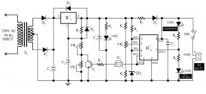
Here is a 12V, 7Ah smart battery charger circuit which is also referred to as a smart charger uses three-stage of charging i.e. bulk stage, absorption stage, and float stage. Normal battery charger technology uses single-stage battery charging technology i.e. only charge the battery up to the maximum charging voltage preset by the charging circuit. Now here is a 12V, 7Ah smart battery charging circuit which is also referred to as a smart charger uses three-stage of charging i.e. bulk stage, absorption stage, and float stage. You may also like Arduino…
Read MoreCategory: power supply
9V DC to plus/minus 5V DC converter
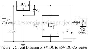
Presented here is a simple circuit “9V DC to plus/minus 5V DC converter” that can convert a 9V battery to plus/minus 5V DC supply using LM7805 and ICL 7660. The operational amplifier requires a dual polarity power supply (+Ve and -Ve) because it has to swing on the output i.e. it does not swing into action during the negative cycle of signal if the negative source is not given. Thus, for the proper operation, we need a dual polarity power supply. Circuit Description of 9V DC to plus/minus 5V DC converter While…
Read MoreMicrocontroller Based Solar Charger
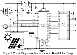
The project ‘Microcontroller Based Solar Charger’ has been so popular, that everyone knows about it. Here we will discuss the construction details and areas where this project is applicable. With excessive non-renewable energy consumption, we humans are facing plentiful difficulties. Renewable sources of energy are considered our only hope to rise from this situation. Solar energy is one of them which have spread all over for its easy availability, effective cost, and reliability. The project, ‘Microcontroller Based Solar Charger’ is the finest example to demonstrate the easy utilization of resources…
Read More12 V Battery Charger with overcharge and deep-discharge protecting
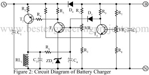
Introduction of 12 V Battery Charger with overcharge and deep-discharge protecting Mostly in broad projects, we have seen lead-acid storage cells are often used as a backup source of electrical energy during periods of supply line failure so that the system operates efficiently. In case of mains supply failure, the energy (i.e. electrical) stored in the cell is used and later when the mains supply is available, the energy in the cell is restored from the mains through a device named a charger. The cell undergoes chemical processes during the charging…
Read MoreAutomatic Voltage Stabilizer Circuit
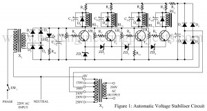
The project posted here is called an automatic voltage stabilizer circuit which solves almost all problems faced in the normally available stabilizer efficiently. With the help of the automatic voltage stabilizer circuit, we can keep the constant voltage at 230V when the voltage goes low as 170V and high as 250V automatically. The working strategy of the Automatic Voltage Stabilizer Circuit The working strategy of the circuit is very simple, this circuit energized one relay at a time from 170V AC upwards, and all relays and energized when 230V AC…
Read MoreOvervoltage Protection Circuit
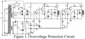
Multiple appliances have been born to ease human efforts. And in the same run, numerous protective circuits are designed to ensure a long lifespan of those devices. We have seen those circuits claiming to protect appliances like refrigerators and air-conditioners from voltage fluctuations and brown-outs. An overvoltage protection circuit has been presented here serving multi-purpose security; under-voltage protection, switch-on delay, and regulation. Description of Overvoltage Protection Circuit Do not get worried with the overvoltage protection circuit diagram, though it looks complex, the circuit comprises building blocks we have been familiar…
Read MoreHigh Current Regulator Circuit
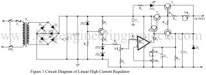
The high current regulator circuit can be delivering up to 3-amp load current continuously. The output voltage can be set in the range of 4V to 22V. Fine variation in the output voltage can also be done using a potentiometer VR3. The output current, ranging from 350mA to 3000mA can be varied by potentiometer VR1. Circuit Description of High Current Regulator Circuit The high current regulator circuit given here utilizes all the advantages of the operational amplifier LM3140 (IC1). It has very high input impedance, high gain, high CMRR, low…
Read MorePower Protection Circuit
Being active users of electrical appliances, we can’t deny the fact that they have almost become our right hand to perform our day-to-day activities. Some of these appliances cost us a heavy amount and when these devices fail to operate or get damaged, we suffer heavy economical loss and in addition to that, we lose our helping hand. To avoid this type of issue faced by most people, we have prepared this low-cost circuit “power protection circuit” which saves our dear electrically operated appliances from situations like sudden tripping and…
Read MoreNon-Destructive Power Supply Circuit
The power supply is the basic unit for any electronic circuit and it must be non-destructive. Various types of power supply circuits like stabilized power supply units, Digital control variable power supply units, self switching off power supply units, etc are available on bestengineeringprojects.com. Now, here is another circuit for smooth power supply in the section of power supply-based projects called a Non-destructive power supply circuit using voltage regulator IC 732. Working of the circuit non-destructive power supply-Circuit Most circuits are set to an adjustable “knee” from 2mA to 30mA.…
Read MoreAdvance Mini UPS Circuit
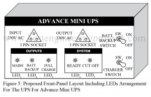
Mobile phones and small electronic gadgets are powered by AC mains using an AC adapter. In the event of mains failure, a low-capacity UPS will do the job satisfactorily. Here we design a simple, efficient, economical, and easy-to-construct UPS for mobile phone or telephone sets. The project advanced mini-UPS circuit can also be used for high power by changing a transformer with a high current rating so this circuit can be used as power backup for laptops also. We have already posted 350VA Offline UPS Circuit. Block Diagram of Advance…
Read More