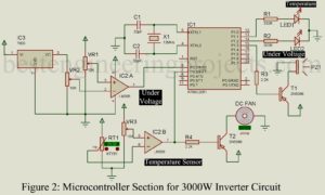
The project posted here is a 3000W inverter with the facility like an inbuilt charger, over and under voltage control, temperature control, microcontroller-based, etc. We all know that an inverter is a device that changes DC power into AC power (just opposite of a rectifier). The general-purpose inverter (low or medium power inverter) used in our house converts 12V DC voltage to 220V AC. But the circuit posted here converts 24V DC (two 12V batteries connected in series) to 220V AC. Circuit Description of Microcontroller Based 3000W Inverter with inbuilt…
Read MoreCategory: power supply
12V DC Ballast Circuit
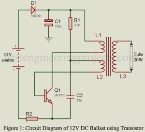
The project “12V DC Ballast” using power transistor 2N3055 is used to glow AC tube light using a DC source. The circuit of DC ballast is a DC-to-AC converter. DC ballast of various capacities (in watts) is already available in markets. The circuit posted here is of 20W capacity i.e. (it can drive a load up to 20 watts). Previously, we had posted Electronic Blast for Tube-light which drives load up to 40W, double the power of 12V DC Blast. Circuit Description of 12V DC Ballast The circuit of 12V DC…
Read MoreAutomatic Night Lamp Circuit
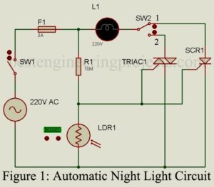
The project “Automatic Night Lamp Circuit” is very simple and built around four major components i.e. TRIAC, SCR, LDR, and Resistor. The lamp used in this project is a porch light that would turn on automatically in dark (nighttime) and turn off in light (daytime). Circuit Description of Automatic Night Lamp Circuit The circuit of Automatic Night Lamp Circuit is used shown in figure 1. The circuit is very simple and straightforward that anyone has very little knowledge about TRIAC and SCR. Silicon Controlled Rectifier | Automatic Night Lamp SCR…
Read MoreAuto Cut Circuit for Over and Under Voltage
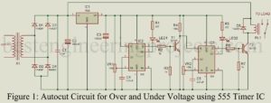
The project “Auto Cut Circuit for Over and Under Voltage” is designed to protect electrical and electronic devices from over and under voltage which ensures a long lifespan of this device. An “Auto Cut Circuit for Over and Under Voltage” has been presented here serving multiple purposes for security; under-voltage protection, over-voltage protection, auto reset, auto cut off, and regulation. Circuit Description of Auto Cut Circuit for Over and Under Voltage The circuit diagram of “Auto Cut Circuit for Over and Under Voltage” is shown in figure 1. The entire…
Read MoreWireless Mobile Charger Circuit Diagram
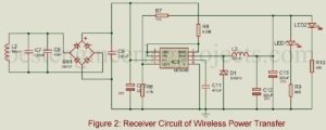
Wireless Mobile Charging is one of the trending topics in the field of electronics thus we also decided to build a Wireless Mobile Charger Circuit Diagram using various commonly available components. The project Wireless Mobile Charger Circuit Diagram posted here can deliver 271mA at 5.2V so you charge mobile phones and also can be used to drive low power loads such as LED1 and LED2 as shown in figure 2. Working Principle of Wireless Mobile Charger Circuit Diagram Wireless Mobile Charger uses the inductive coupling principle. In this principle, two…
Read MorePower Saver Circuit Diagram using PIR
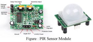
People are always in rush these days and they forget important things like turning the lights off in addition to a few other electrical devices. This results in either an electrical explosion or wastage of power. And, so to eradicate such issues, we have developed a Power Saver Circuit Diagram based on a Passive infrared sensor that employs a PIR motion sensor to detect the presence of human beings and as they leave the room, turn any electrical appliances connected to the circuit after a certain defined time interval. The…
Read MoreAC Voltage Stabilizer Circuit using 556 IC
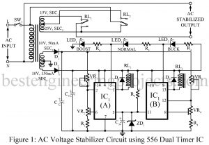
AC Voltage Stabilizer Circuit using 556 IC Various types of AC voltage stabilizer circuits had already been posted on bestengineeringprojects.com like Versatile Auto Cut-off Unit Automatic Voltage Stabilizer Circuit Overvoltage Protection Circuit The circuit posted here is a cheap, versatile, and high-performance AC voltage stabilizer using dual timer IC 556 IC. The circuit makes use of most of the features of dual timer IC 556, namely, the four voltage level comparators, two high current sourcing/sinking outputs, two discharge transistors, and the ability to provide hysteresis with the help of its…
Read MoreCar (Automobile) Battery Maintaining Circuit
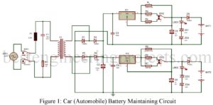
Here is a simple circuit built around very common electronics components easily available in the local market which is used to protect car (automobile) batteries from deep discharge and also protect from getting damaged. Let’s get some facts about automobile batteries. We all know that battery itself has some self-discharge rate which depends upon battery capacity and the materials used to make it. Various reasons discharge a battery like an electrical installation in a car. When we do not use our automobile for a longer period the battery becomes fully…
Read MoreDual Polarity 5v from 9v Battery
Almost all electronic devices used in electronic circuits need a dc source of power to operate. The source of dc power is used to establish the dc operating point for the passive and active electronic devices in-corporate in the system. This day almost all circuits 5V regulated power supply but an operational amplifier requires a dual power supply (positive and negative) for proper operation, while we are using the battery power supply for a circuit then it would be difficult to get a dual polarity power supply. In order to…
Read MoreElectronic Fuse Using Op-amp 741
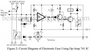
Here is an electronic fuse using op-amp 741 which features slow-blow properties, a variable current limit, and a ‘live’ indication of its operation. Moreover, it is simple to restore. The electronic fuse using op-amp 741 allows the gadget to draw a higher current initially but keeps a watch on it. if the gadget continues to draw more current beyond the set time limit, it disconnects the supply. The fuse, therefore, acts as a cut-out and indicates this by a neon glow. It is replaced by simply resetting the circuit once.…
Read More