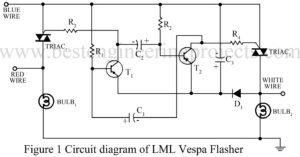
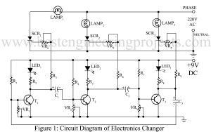
Replacement of burnt LML vespa flasher costs around $ 2.5. The flasher can be replaced with the help of the circuit sows here. It costs around $1.2. Circuit Description of LML Vespa Flasher The circuit of LML vespa flasher consists of a multivibrator built around transistors T1 and T2. The time period of the pulse can be varied by changing the values of R1, R2, C1 and C2. The values shows in the circuit are chosen to match the flasher with the flashers available in the market. Gates of TRIAC…
Read MoreCategory: Basic Electronic Projects
Different electronic project for entry level which are easy to build and understand.
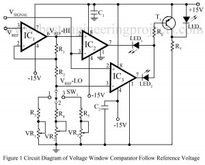
Voltage window comparator Circuit follows reference voltage
The use of window comparators are essential in the test circuits which perform the ‘GO-NO-GO’ tests for the various electronic components likes zener diodes, transistors, relays etc. The upper and lower threshold voltages are set for the window comparators depending upon the values and tolerances of the components to be tested. Here is a window comparator circuit in which the window width is automatically adjusted to be a fixed percentage of the input reference voltage Vref proportional to the nominal value of the component under test and produces an upper…
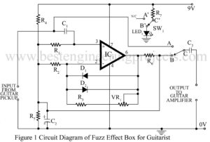
Read MoreFuzz effect box for Guitarists
The ‘fuzz’ sound is derived by clipping the input waveform, thereby enriching the signal with odd harmonic which provide the hash sound. This circuit “Fuzz Effect Box for Guitarists” is a basic project produces a fuzz which gradually decays into a ‘clean signal’. Circuit Description of Fuzz Effect Box for Guitarists The circuit uses the standard op-amp 741 in non-inverting configuration. The gain of this amplifier is controlled by the feedback network comprising VR1, R2 and R3. Input signal from the guitar passes to the op-amp through DC blocking capacitors…
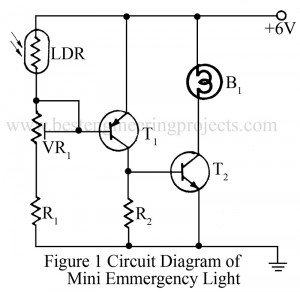
Read MoreMini Emergency Light Circuit
There are various type of emergency light circuits. Every circuit has its own importance and utility. But size, cost and efficiency of the circuit are some of the main feature of interest. A very simple circuit of mini emergency light is given here. In normal daylight or electric light, the LDR offer very low resistance. So the positive voltage is applied to the base of transistor T1, making it reverse biased. Therefore, T1 does not conduct in presence of light. As transistor T2 also is reverse biased it does not…
Read MoreElectronic Ballast Circuit
The fluorescent tube-light requires additional gear such as the copper ballast and starter for normal operation. These two are required to provide the initial high voltage for ionization and thereafter to limit the current through the tube to safe values. It has been observed that the illumination efficiency of the tube-light when excited by high frequency power source is higher than that when excited at the 50Hz line frequency. Moreover, the power factor and the efficiency of the bulky copper ballasts are poor. Hence, electronic ballasts circuit were developed to…
Read MoreExpander Compressor Unit Circuit | Compander
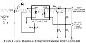
The compression and expansion are two important techniques used by audio engineers during recording and reproduction of program material. The compression of dynamic range of program material (records, speech or musical broadcasting) permits maintaining constantly high modulating level while the expansion, when used with the reproduction of compressed material, restores the dynamic range and creates a ‘live’ music. Thus, we are created simple and basic project Expander Compressor Unit Circuit. Circuit Description of Expander Compressor Unit Circuit | Compander Creating these effects is costly and complex, and beyond the scope of amateur…
Read MoreHearing Aid Circuit
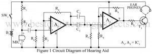
The hearing aid circuit available in the market are fully transistorized and generally use a single pen cell. The hearing aid circuit uses an IC LM358 (IC1) for the same purpose which give better sensitive and performance. You can also check DIY Hearing Aid Circuit using 555. Circuit Description of Hearing Aid Circuit Operational amplifiers are used here in their simplest from non-inverting AC amplifier with a gain of 100. Op-amp A1 forms the first-stage amplifier. Second-stage amplification is given through op-amp A2. Hence the total gain is 10,000. Resistors…
Read MoreAudio Running Lights Circuit
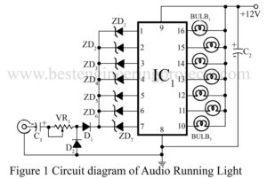
Here is a project for audio running lights circuit which uses filament bulbs instead of LEDs. The circuit employs seven channel darlington array IC ULN2004 and seven reversed biased zener diodes having different breakdown voltages. At low audio level, zener diodes having low breakdown voltages will conduct and corresponding lamps will light up. When output level increases, the other diodes will also conduct. As a result, you can see a very fine display of ‘moving’ light bulbs from top to bottom or from left to right, as per their arrangement.…
Read MoreRunning Light Circuit
In many situations, whenever a running light effect is required, a wooden wheel switch is needed. The wheel is driven by a motor which normally connects three switches, one by one producing a running light effects. Such a switching is very bulky and troublesome. Here is a simple electronic project “Running light circuit” with a very few components but which is equally effective. Circuit Description of Running Light Circuit In the circuit running light all transistors remain on except one which is off. This off sequence ‘travels’ through each transistor.…
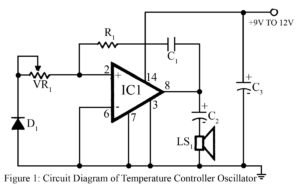
Read MoreTemperature controlled oscillator Circuit
Output frequency or tone of the project temperature controlled oscillator circuit varies with the temperature at which the input germanium diode is held. Reverse resistance of D1 varies from 500-Ω to 10 KΩ, when temperature varies between 200C and 800C. (At higher temperature germanium devices show very low resistance.) This variation of resistance changes the tone of the output sound of the oscillator which is built around the AF amplifier IC (IC1). Instead of germanium diode, base-emitter junction of an ordinary medium-power transistor such as AC128, AC188, 2N360 or 2N610…
Read More