Here is a project for audio running lights circuit which uses filament bulbs instead of LEDs. The circuit employs seven channel darlington array IC ULN2004 and seven reversed biased zener diodes having different breakdown voltages.
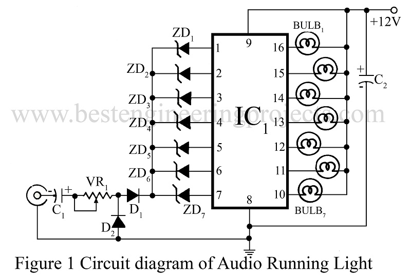
At low audio level, zener diodes having low breakdown voltages will conduct and corresponding lamps will light up. When output level increases, the other diodes will also conduct.
As a result, you can see a very fine display of ‘moving’ light bulbs from top to bottom or from left to right, as per their arrangement.
AF input signal fed via capacitor C1 is rectified by diodes D8 and D9. This rectified audio signal is given to the cathodes of all zener diodes.
Adjust VR1, for satisfactory operation of the IC. At minimum input the first lamp will glow and at maximum input all the bulbs will light up.
PARTS LIST
|
Resistors (all ¼-watt, ± 5% Carbon unless stated otherwise) |
|
VR1 = 10 KΩ |
|
Capacitors |
|
C1 = 220 µF/25V C1 = 470 µF/25V |
|
Semiconductors |
|
IC1 = ULN 2004 D1, D2 = 1N4148 ZD1 = 1.2 V zener diode ZD2 = 2.7 V zener diode ZD3 = 3.6 V zener diode ZD4 = 4.5 V zener diode ZD5 = 6.8 V zener diode ZD6 = 9.1 V zener diode ZD7 = 12V zener diode |
|
Miscellaneous |
|
Bulb1 – Bulb7 = 12V bulbs |