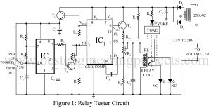
Here is the relay tester circuit using timer IC 555 which is used to measure pull-in and release voltage of relays ranging from 6V to 28V DC. Relays are probably the simplest electromechanical devices, yet they are the most important components of many industrial and domestic electrical equipment. All too often, it is a hardship for the equipment manufacturers to discover that the commercial quality relays of similar types have a wide range of operating voltage. Many times, it is found that the relay contacts will not close properly. Many…
Read MoreCategory: 555 Timer Projects
Sound Operated Intruder Alarm with Flash
Sound Operated Intruder Alarm with extra features like a flashlight, circuit diagram, description with working principle, and parts list. Introduction to Sound Operated Intruder Alarm with Flash If you have already gone through the previous project Op-amp 741 Based Sound operated Light on our website, then for you this project is a transformation of that generalized project into a specialized intruder’s alarm project. Why should one invest much effort, time, and money to recreate a new circuit when a slight modification to the existing project works fine? This is the core…
Read MoreFire Alarm Using Thermistor and NE555
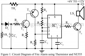
If we search for fire alarm circuits on the internet, we can find a long list of such circuits. Most of those circuits are quite expensive and also the components may not be easily available. So, here we have presented a simple and inexpensive project of ‘fire alarm using thermistor and NE555’. Where a thermistor is the main component and is used as a temperature sensor of the fire alarm. Talking about the working principle of a thermistor, it works in the same way a normal LDR would work i.e.…
Read MoreAutomatic Plant Watering System Circuit
If you are one of those people who would like to spend your well-earned summer vacation in the comfort of a hill resort but are worried about your potted companions back home, then a plant watering system is what you need. The project, “Automatic Plant Watering System Circuit,” immediately waters the plant once the soil becomes dry. By adding timer circuits and other components, we can enhance the flexibility of this project and make further improvements, allowing it to operate automatically for the duration set by the timer. Circuit Description…
Read MoreMachine Sound Generator Using 555 Timer IC
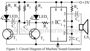
Countless projects have been developed with a variety of alarming effects. We prefer different sound effects in different places. For instance, in security-based projects sharp and alarming sound is considered the best option, whereas, in the doorbell, the soft sound is found pleasant to the ears. Thus, it is more appropriate to have related sound effects for particular areas. The project “Machine Sound Generator Using 555 Timer IC” is a similar project aiming to generate machine sound solely for industrial applications. However, the circuit Machine Sound Generator Using 555 Timer…
Read MoreBeeper for Automobile Flasher Using 555
Flashing light is a good way to alert people around but is not the best measure. Ears can hear when eyes cannot see. Therefore using a beeper circuit is the best remedy and this concept has been utilized in modern automobiles and also included in multiple other applications. The project ‘beeper for automobile flasher’ can be implemented in old automobiles (scooters, motorcycles) where there is no beeper circuit along with a flasher. It can also be included in many other alerting projects which employ flasher circuits. Working of Beeper for…
Read MoreGrasshopper Sound Generator Circuit using 555 Timer IC
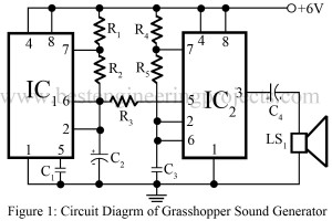
Electronics projects just because of the name must not, always be complicated and advance level projects. Small projects play a vital role in the field of electronics. Here is a similar basic project which is named, ‘Grasshopper Sound Generator Circuit Using 555’. The project will surely entertain children and for electronics beginners, this project is the best option to start with. Especially at night times, we do often hear the shrill sound of grasshopper or cockroach. This project also produces a similar sound (PI-PI sound like grasshopper) and for this…
Read MoreChristmas Decoration Circuit With Music
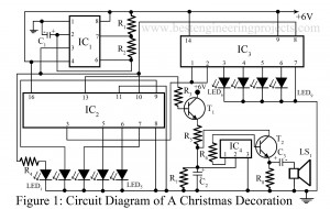
Simply, by name of the project ‘Christmas Decoration Circuit With Music’ it can be easily understand that this project is concerned about decoration. Different kinds of item are available nowadays in the market for decoration. Where you can buy/pick one of the item from market or you can make it one. The interest lies on the things you have created with yours owns. Definitely, this project is your interest and can be used in Christmas decoration. Circuit Description of Christmas Decoration Circuit With Music : – The circuit of Christmas…
Read More555 Timer IC Tester
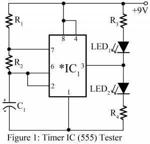
NE555 Timer IC is very popular and one of the most commonly used components in electronics circuits. NE555 Timer IC is also called Ideal IC since it offers multiple features like multipurpose functionality, low power consumption, small size, and durability. When we work on a particular project and it doesn’t work the way we wanted, before the circuit we doubt whether the IC used, is working or not. More or less, blaming IC is reasonable since IC is the combination of many more components or IC itself is a combination…
Read MoreLED Chaser Circuit Using NE555
Various types of LED-based projects are already posted on bestengineeringprojects.com. Now, here is a simple project called LED chaser Circuit using NE555 in which 10 different LED is arranged in a column. The LED arranged in column glow from top to bottom, one at a time. Description of LED Chaser Circuit Using NE555 The circuit of the LED chaser is designed around a timer IC NE555 (IC1) and decade counter IC CD4017 (IC2). Here, IC1 is used in astable multivibrator mode which generates a clock pulse in a fixed interval…
Read More