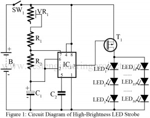
Dome Lamp Dimmer Circuit

circuit diagram of dome lamp dimmer

As we have already published various types of lamp dimmer like Light Dimmer Circuit using Capacitor and Touch Dimmer Circuit using triac etc. Now here is a lamp dimmer for the dome lamp in the car, which gives a fairly linear control over the lamp brightness from low to high intensity. The main advantage of the project dome lamp dimmer circuit is it consumes little power because it is a pulse-width modulated chopper circuit. You can also control the intensity of a halogen bulb or control the speed of a…

Read More

Clap Switch Circuit Using 555

circuit diagram of clap operated electronics switch

The clap switch circuit is not a new idea for the electronics hobbyist. Previously we had posted a simple clap-operated switch. Now, here is a clap switch circuit using 555, used to control any appliance by clapping five times. We used here decade counter for the right clap code i.e. only the right clap activates the appliance (five claps within the preset time interval of 10 seconds). Description of Clap Switch Circuit Using 555 The clap switch circuit using 555 is built around timer IC 555, decade counter IC CD…

Read More

Running and Spellar Effects of Light Circuit

running and spellar effect light circuit

There are many display circuits already published in BEP. But the circuit Running and Spellar Effects of Light Circuit is very special in its own way because it contains all the facilities required for any type of decoration. Lighting decoration broadly consists of two main categories-the running effect and the spellar effects. Running effect is well known to every electronics hobbyist. The spellar effect consists of many output driving the load-lamps; all of them go high one after another, and eventually all outputs becomes high simultaneously showing a complete display.…

Read More

Ten Channel Sequential Lighting Circuit

ten channel sequential lighting circuit

The project Ten channel Sequential Lighting presented here gives a flashing light effect from left to right and then from right to left. IC1 (NE555) generates clock pulses for IC2. The output using rectifiers produce the effect of bulbs flashing from left to right. As the carry output pin 12 of IC2 is connected to the clock input of IC3, the bulbs which are connected to IC5 also starts flashing from right to left. As these outputs are not capable of handling large currents, they have to be amplified to…

Read More

Dynamic Display Ads Circuit

dynamic display circuit

This project of “Dynamic Display Ads Circuit” is based on serial input and parallel output sift register 74164. With the help of the project dynamic display ads circuit we can build a display board, where LEDs blink to give a running light effect. Circuit Description of Dynamic Display Ads Circuit The project dynamic display ads circuit may be used to advertise or display of name plates etc. It is made versatile by using the 555 and 74 series of ICs, which are readily available in the market. In the dynamic…

Read More

Automatic Time Indicator for Telephone

circuit arrangement for telephone

The circuit Automatic Time Indicator for Telephone presented here provides an audible warning 2.5 minutes after dialing the telephone. The circuit does not make use of telephone line for its operation. Circuit Description of Automatic Time Indicator for Telephone The circuit consists of three 555 ICs. It can be divided into three parts- touch switch using IC1, timer using IC2 and oscillator using IC3. The on touch plate is in the form of a wire, the insulation of which is attached to the stopper on the telephone dial. The off touch…

Read More

3 Phase Induction Motor Starter

3-phase automatic induction motor starter circuit

This circuit “3 Phase  Induction Motor Starter” is one such starter. It is a very low-cost but highly reliable gadget, besides being fool-proof. Of all AC motors available, a polyphase induction motor is one that is mostly used in several kinds of industrial drives. this is because it is simple, extremely rugged, low cost, reliable, high efficient and requires little maintenance. Among the induction motors available, a squirrel cage machine is the best. However, such an induction motor can never be started by direct switching, as the motor can never…

Read More

Auto-off for Cassette Players

auto off for cassette players

Most common stereo cassette players have an auto-stop deck mechanism but do not have the auto power-off function. The circuit is meant for cassette players having an operational voltage of 12 V DC with the facility of LED type VU meter. When the sound signal stops, the power is automatically switched off after a delay of approximately 30 seconds. Circuit Description of Auto-off Cassette players With sound present, the LEDs of VU meter emits light. The LDR on receiving light from LEDs gives a high pulse to transistor T1which charge…

Read More

Multi-Pattern Running Light Circuit

multi pattern running light

Running lights effect is not a new idea for electronics  hobbyist. But this multi-pattern running light becomes unique as four patterns can be selected. In the first pattern, out of eight lights, alternate light go ‘on’ and ‘off’. In the second pattern, two adjacent lights go ‘on’ and the following two go ‘off’. This pattern is shifted from left to right. In the third pattern, four adjacent lights go ‘on’ and these are sifted to right. In the fourth pattern all the eights light go ‘on’ and ‘off’ one by…

Read More

Simple Power Supply Resumption Alarm

simple power resumption alarm

Once again the most popular timer IC NE555 proved that its applications are limited only to the user’s ingenuity. The circuit of the simple power resumption alarm shown here is straightforward, where IC1 is wired in a special kind of mode. Circuit Description of Simple Power Supply Resumption Alarm When the power supply resumes, pin 2 of IC1 is grounded through C1 and pin 3 goes high. This makes reset pin 4 go high for about 10 seconds. When the capacitor C1 charges to two-thirds of the supply voltage, the output…

Read More